Landing area clear of aircraft or any other
obstructions
Aircraft recovery green rotating beacon on
All stations manned and ready with voice
communication established and reports made to
the air officer
Sheave and anchor damper in the battery
position
All engines fully retracted and crossdeck
pendant at the proper height
Engine fluid levels in the battery range and
accumulator pressure at 400 psi
Received from the air officer; aircraft type to be
recovered
Determine proper aircraft weight setting in
accordance with applicable aircraft recovery
bulletin
Direct the engine room operators to set their
respective engine and verify that correct weight
has been set
Pickle switch is actuated, lighting the green clear
deck landing status light
NORMAL RECOVERY OPERATIONS
Normal recovery operations involve the recovery of
aircraft with no equipment failure or damage that
precludes the aircraft from recovering at the prescribed
air speed or proper landing configuration.
3-3
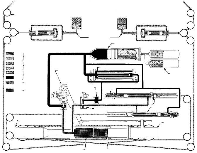
DECK SHEAVE
ABEf0302
DAMPER SHEAVE
INSTALLATION
ACCUMULATOR
AIR EXPANSION
FLASK
COOLER
CONSTANT RUNOUT
CONTROL VALVE
FILTER
CABLE ANCHOR
DAMPER
CROSSHEAD
RAM
CYLINDER
RETRACTION VALVE
FIXED SHEAVE
AIR
FLUIDZERO PRESSURE
750 PSI TO
1500 PSI
400 PSI TO
650 PSI
750 PSI TO
3000 PSI
400 PSI TO
10000 PSI
LEGEND
AIR
FLUID
AIR
FLUID
FLUID
FLUID
Figure 3-2.—Mk 7 Mod 3 fluid flow diagram during arrestment.


