
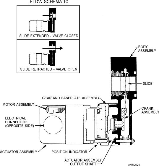
Figure 12-26.--Motor operated shutoff valve.
Electric Solenoid Shutoff Valve
CONDITON TWO (FLIGHT).--Flight control
system pressure normal, switch in the flight position,
The shutoff valve, shown in figure 12-27, is used to
solenoid energized, and the pilot ball on its upper seat,
shut off the fluid flow to selected subsystems of a
preventing the pressure of the flight control system
utility hydraulic system. It can also limit the use of all
from working on the lower working area to the poppet.
available utility system pressure for the operation of
See figure 12-27, View B. In this condition, the return
the primary flight controls or prevent fluid loss during
port of the flight system is open. The poppet spring
flight when damage to the utility system has occurred.
will move the poppet onto its seat, preventing the fluid
This valve is sometimes referred to as a priority valve
from the utility system from flowing downstream from
and normally has three modes or conditions of
the location of the valve. This allows all available fluid
operation.
to be directed to the components of the utility section,
CONDITION ONE (LANDING).--Flight
such as the ailerons, rudder, stabilizer, spoilers, of the
control system pressure normal, switch in the landing
flight control subsystem.
position, solenoid deenergized, and the pilot ball on its
CONDITION THREE (EMERGENCY).--
lower seat, blocking the return port of the flight control
Failure of the flight control hydraulic system. The
system. See figure 12-27, View A. In this condition,
flight control system pressure is 0 psi, and the utility
the pressure of the flight control system is allowed to
system pressure is normal. During this condition, the
act upon the lower working area of the poppet, moving
poppet will remain on its seat, because the pressure of
it upward off its seat and compressing the poppet
the flight control system is not available to work on the
spring. This action will allow the fluid of the utility
lower working area of the poppet to move it up to open
system to flow downstream from the location of the
valves to the landing gear, flaps, speed brakes, etc.
the valve. See figure 12-27 View C.
12-25