
Figure 12-22.--Motor-driven variable displacement piston pump schematic.
around the motor through the hollow-walled motor
provide more or less flow. Whereas engine-driven
case, after which it is directed by an external line into
pumps are generally rated to produce a given pressure
the case of the piston pump. This constant flow
and flow at a nominal drive speed, the electric
through the low-pressure chamber of the main pump
motor-driven pump has a fixed rotational speed and a
cools and lubricates all of its moving parts. It also
special compensating mechanism that enables the
p i c k s u p " b l ow - b y " o i l t h a t e s c a p e s p a s t t h e
pump to provide 6 gpm (gallons per minute) at 2,950 to
high-pressure pump pistons, and is discharged through
3,000 psi. It will provide more flow as system pressure
a coarse-screen filter cartridge installed in the case
drops, reaching a maximum flow of 8 gpm at 2,200 psi.
drain port. The pump's coolant flow is routed through
The accelerated flow enables the system to maintain
the aircraft's heat exchanger and back to the reservoir.
normal speed of many actuators in use simultaneously.
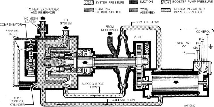
The second delivery point from the integral
Figure 12-23 shows the three phases of pump
centrifugal pump is directed from the centrifugal pump
compensation in a pressure buildup order, starting at
scroll at positive pressure to the intake port of the
low pressure and increasing to full system pressure. As
high-pressure pump. As you can see in figure 12-22,
shown in view (A), the yoke control piston is spring
the Vickers motor-driven variable displacement design
loaded to hold the displacement yoke at its maximum
is similar to other engine-driven designs. The rotating
displacement angle of 30 degrees. This spring is
assembly consists of a baseplate, to which nine piston
opposed by the existing system pressure, which acts at
rods are joined. The assembly turns in a fixed plane.
all times on the "constant horsepower" piston area;
Also turning with it is a cylindrical nine-piston block
however, the hydraulic force will not be sufficient to
fitted inside a nonrotating yoke. The yoke is
move the yoke control piston until the actuating
pivot-mounted to the pump case, and has an offset
pressure (system pressure) builds up to 2,200 psi.
attachment for a compensator piston rod that controls
Thus, the cylinder block will be canted to its maximum
the yoke's attitude. If the yoke is not deflected, the
angle, and the pump will deliver its maximum flow, 8
cylinder block containing the pistons will rotate in a
gpm, when system pressure is less than 2,200 psi.
plane parallel to the baseplate, thus producing no
View (B) of figure 12-23 shows how the yoke
stroke. The yoke can be tilted to displace the pistons,
control piston responds to system pressure fluctuations
reaching maximum stroke when the yoke is tilted 30
in the 2,200 to 2,950 psi range. Assuming that system
degrees from the plane of rotation of the baseplate.
pressure is steadily increasing, the displacement yoke
The pump compensating mechanism receives a
angle will decrease from the 30-degree full
feedback signal of system pressure, and adjusts the
displacement angle to approximately 22 degrees,
pump output by tilting the yoke a prescribed amount to
which will produce 6 gpm at 2,950 psi.
12-20