
one, this plug must be removed and the housing filled
The following installation procedures are typical
examples:
with fluid before the pump is operated. There is a drain
port in the mounting flange to drain away any leakage
1. Place the pump on the aircraft structure
from the drive shaft oil seal.
mounting pad. Connect the pressure and suction lines to
the pump ports and tighten the "B" nuts fingertight.
When the drive shaft is rotated, it rotates the
pistons and cylinder block with it. The offset position
2. Align and install the mounting screws/bolts.
of the cylinder block causes the pistons to move back
3. Tighten the "B" nuts to the correct torque
and forth in the cylinder block while the shaft, pistons,
values.
and cylinder block rotate together. As the pistons move
back and forth in the cylinder block, they draw the fluid
4. Attach the electrical connection to the motor.
in one port and force it out the other. This action
5. Service the reservoir to the proper level.
creates a steady, nonpulsating flow of fluid. Certain
6. Perform operational check according to the
models of this pump are capable of developing up to
applicable MIM.
3,000 psi working pressure.
NOTE: Prior to the installation of hydraulic units,
Constant displacement pumps of this series are
the preservation fluid must be drained and the unit
designed so they can be driven in either direction. The
flushed with clean hydraulic fluid.
direction of rotation of the pump must coincide with
the engine accessory section. The pump rotation can
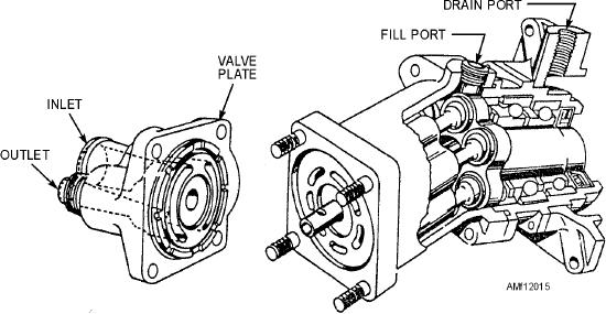
P I S T O N - T Y P E P U M P ( C O N S TA N T
be determined by referring to an arrow on the pump
D I S P L AC E M E N T ) . -- P i s t o n - t y p e c o n s t a n t
housing adjacent to the valve plate. The only change
displacement pumps consist of a circular cylinder
necessary when changing the direction of rotation of
block with either seven or nine equally spaced pistons.
the pump is to rotate the valve plate 180 degrees.
Figure 12-15 is a partial cutaway view of a seven-
piston pump manufactured by Vickers, Incorporated.
Before installation, the pump mounting flange and
shim, if used, must be wiped clean. The pump must be
The main parts of the pump are the drive shaft,
primed by filling the housing with hydraulic fluid
pistons, cylinder block, and valve plate. There are two
through the fill port. The exposed drive shaft spline
ports in the valve plate. These ports connect directly to
should be lubricated. To ensure internal cleanliness,
openings in the face of the cylinder block. Hydraulic
the shipping plugs should not be removed until the
fluid is sucked in one port and forced out the other port
lines are ready for attachment.
by the reciprocating (back-and-forth) motion of the
pistons.
Normally, for repair, the pump should be shipped
t o a n i n t e r m e d i a t e - l ev e l a c t iv i t y ; h ow ev e r,
There is a fill port in the top of the cylinder
replacement of packings and gaskets can be
housing. This opening is normally kept plugged, but it
accomplished in the field. To prevent damage in the
can be opened for testing the pressure in the housing or
case. When you install a new pump or newly repaired
event of the pump binding, a shear section is
Figure 12-15.--Partial cutaway view of piston-type pump.
12-15