
3. Eliminates the need of using a test stand to drop
motor from overheating. The reset button will open
and stop the motor when the temperature exceeds 380
check the landing gear and perform operational
10F. If the motor does not restart after cooling, the
checks of other actuating systems.
cover plate over the reset button should be removed and
NOTE: Hydraulic test stands are seldom used on
the reset button reset manually. If the motor still fails to
aircraft that incorporate this type of pump because
start, the motor pump assembly should be replaced.
foreign particles could be transferred from the test
The motor-driven variable displacement pump
stand to the aircraft, thus contaminating the hydraulic
system.
suction line is connected from the reservoir to the
suction port of the pump assembly, where fluid is
4. The pump assembly contains an internal
ported into the center of a centrifugal pump scroll. The
centrifugal boost pump, which provides a
scroll is located between the main pump case and the
positive fluid pressure at the suction port of the
motor reduction gearbox of the pump assembly. See
variable displacement pump.
figure 12-21. The scroll houses a centrifugal booster
pump, which is mounted directly on the main pump
The only disadvantages of the pump are the size of
shaft. The constant-speed motor turns the pump shaft
the complete assembly and its weight. For this reason,
through reduction gears at 3,200 rpm, which is
this type of pump is used in patrol and transport
sufficient to boost the fluid pressure about 15 to 20 psi
aircraft.
above the existing reservoir pressure. The output of
There are other features incorporated in the
this integral pump is directed to two points on opposite
motor-driven variable displacement pump that you
sides of the scroll housing. See figure 12-22.
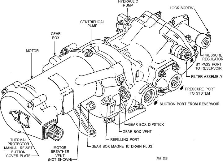
should know about. A thermal protector manual reset
One delivery point provides a constant flow of
button is installed on the end of the motor, which is
hydraulic fluid for motor cooling through an internal
concealed by a cover plate. See figure 12-21. This
thermal protector is a safety device that protects the
passage. Finned baffle-like passages direct this flow
Figure 12-21.--Motor-driven variable displacement piston pump.
12-19