Home
Download PDF
Order CD-ROM
Order in Print
Figure 12-22.--Motor-driven variable displacement piston pump schematic.
Main System Relief Valves
Aviation Structural Mechanic (AM)
Page Navigation
407
408
409
410
411
412
413
414
415
416
417
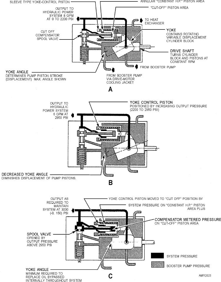
Figure
12-23.--Pump
compensation.
(A)
full
flow
position;
(B)
reduced
flow;
(C)
minimum
flow.
12-21