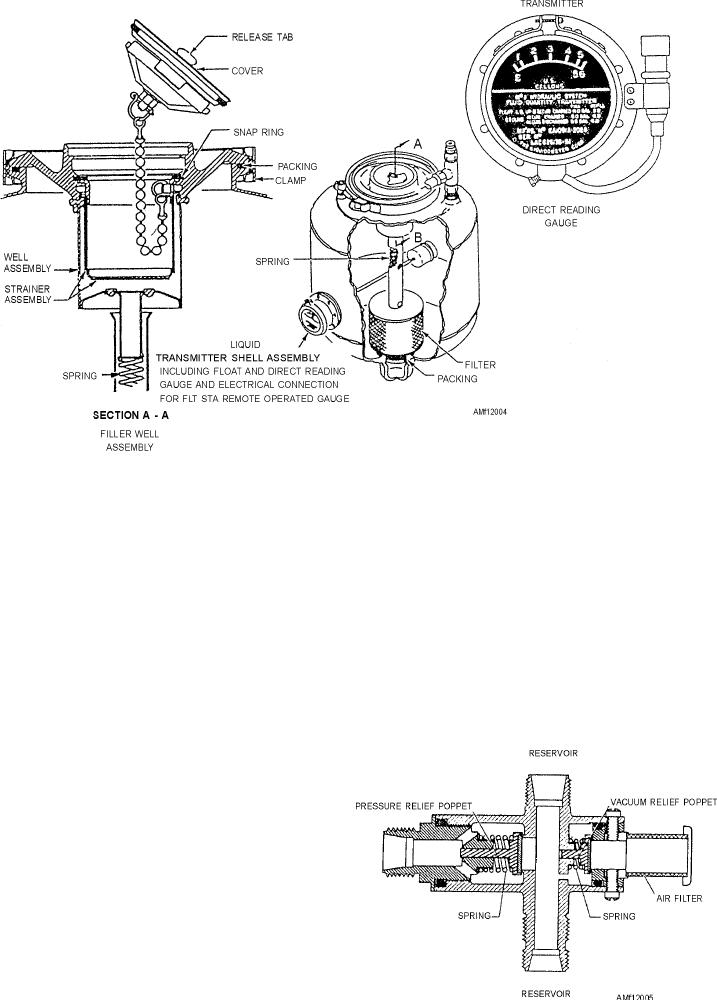
Figure 12-4.--Nonpressurized reservoir.
fluid and the return of fluid to the reservoir from the
incorporated t o s e a l a g a i n s t l e a k a g e b e t w e e n
main system.
assemblies.
Most reservoirs of this type are vented directly to
QUANTITY INDICATING GAUGE.--The
the atmosphere or cabin with only a check valve and
reservoir fluid quantity is indicated through a
filter to control the outside air source. The reservoir
mechanically operated float and arm (liquidometer)
system includes a pressure and vacuum relief valve.
type of unit. The quantity gauge is mounted directly on
The valve, as shown in figure 12-5, has two reservoir
the side of the reservoir. As shown in figure 12-4, the
ports, and it is connected between and serves both main
float and arm unit extends into the reservoir. The shell
system reservoirs. The purpose of the valve is to
of the liquidometer provides a glass window over a
maintain a differential pressure range between the
pointer and dial, with the pointer mechanically linked
reservoir and cabin.
to the float arm. As the float arm moves to correspond
to the fluid level, the pointer, through mechanical
linkage, moves to indicate the quantity available. This
provides a direct reading sight gauge at the reservoir.
This same float movement actuates the
potentiometer wiper arm of an integral transmitter
potentiometer. The remote indicating circuit is
energized, and a duplicate indication of the reservoir
fluid quantity may be seen in the cockpit on a remote
gauge.
RESERVOIR PRESSURE AND VACUUM
RELIEF VALVE.--Although the reservoir shown in
figure 12-4 is classified as a nonpressurized type, it has
a sufficient amount of pressurization to ensure a
positive flow of fluid to the pump suction ports. The
Figure 12-5.--Pressure and vacuum relief valve.
pressurization is derived from thermal expansion of
12-8

