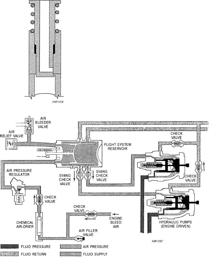
full sectional view of a manual air bleed valve.
RESERVOIR MANUAL AIR BLEED (VENT)
Pressing the slide valve opens a passage to vent the
VALVE.--A vent valve is provided to vent the
reservoir.
reservoir. This valve is connected to the reservoir vent
line to allow depressurization of the reservoir.
Air-Pressurized Reservoirs
The valve is actuated prior to servicing the
reservoir to prevent fluid from being blown out of the
Air-pressurized reservoirs are currently used in
filler as the cap is being removed. Figure 12-6 shows a
many high-performance naval aircraft. Figure 12-7
s h ow s a hy d r a u l i c p ow e r s y s t e m w i t h a n
air-pressurized reservoir incorporated. This system is
similar to the one found on many aircraft; however, for
clarification in the discussion of the operation of the
system, we have deleted some components between
the reservoir and the pump.
The reservoir is cylindrical in shape and has a
piston installed internally to separate the air and fluid
chambers. The piston rod end protrudes through the
reservoir end cap and indicates the fluid quantity. The
quantity indication may be seen by inspecting the
distance the piston rod protrudes from the reservoir
end cap. The reservoir has threaded openings for the
connection of fittings and components. The schematic
shown in figure 12-7 shows several components
installed in lines leading to and from the reservoir;
however, this may not be the case in the actual
installation. The air relief valve, bleeder valve, etc.,
Figure 12-6.--Manual air bleed valve.
may be installed directly on the reservoir.
Figure 12-7.--Air-pressurized reservoir and components.
12-9

