
as the piston is returned to the OFF position by the
pressure of the brake piston return springs.
Any pressure or excess volume of fluid is relieved
through the compensating port and passes back to the
fluid reservoir. The compensating port assures against
dragging or locked brakes.
If any fluid is lost back of the front piston seal due
to leakage, it is automatically replaced with fluid from
the reservoir by gravity. Any fluid lost in front of the
piston from leaks in the line or at the brake is
automatically replaced through the piston head ports,
and around the lip of the front piston seal when the
piston makes the return stroke to the full OFF position.
The front piston seal functions as a seal only during the
forward stroke. These automatic fluid replacement
arrangements always keep the master cylinder, brake
connecting line, and brake assembly fully supplied
with fluid as long as there is fluid in the reservoir.
The rear piston seal seals the rear end of the
cylinder at all times to prevent leakage of fluid. The
flexible rubber boot serves only to keep out dust.
Provision is made for locking the brakes for
parking by a ratchet-type lock built into the mechanical
linkage between the master cylinder and the brake
pedal. Any change in the volume of fluid, due to
expansion while the parking brake is on, is taken care
of by a spring incorporated in the linkage. The brakes
are unlocked by application of sufficient pressure on
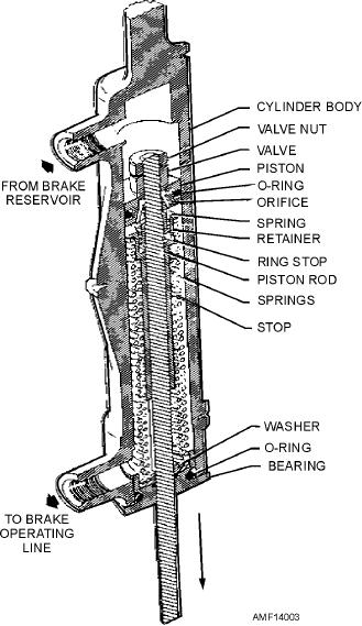
Figure 14-3.--Gladden master brake cylinder.
the brake pedals to unload the ratchet.
Brake systems employing the Goodyear master
the valve to seat and close the piston orifice. This
cylinder must be bled from the top down. In no case
movement also forces fluid into the brake's pressure
should bleeding be attempted from the bottom up,
line to the wheel brake assembly, thus applying the
because it is impossible to remove the air in back of the
brakes.
piston seal.
When the pedal pressure is released, the springs
return the valve and the piston to their neutral position.
Gladden Master Cylinder
The retracting brake assembly piston forces the return
fluid back through the piston orifice to the brake
The Gladden master brake cylinder consists of a
reservoir.
cylinder body, valve, piston, piston rod, return springs,
and a stop assembly, as shown in figure 14-3. The
POWER BOOST BRAKE SYSTEM
piston rod extends through the valve, the piston, the
stop assembly, and the return springs, and is connected
As a general rule, the power boost brake system is
by an eyebolt to the brake arm on the rudder pedal.
used on aircraft that land too fast to use the
When the cylinder is in neutral, the valve is not
independent-type system, but are too light in weight to
seated. Fluid from an independent brake reservoir
require the power brake control system. In this type of
enters the cylinder's reservoir port. Fluid entering this
system, a line is tapped off from the main hydraulic
port is allowed to flow through the piston and fill the
system pressure line, but main hydraulic system
lower chamber.
pressure does not enter the brakes. Main system
pressure is used only to assist pedal movement. This is
When the rudder pedal is depressed by toe
accomplished by using power boost master cylinders.
pressure, the piston rod is pulled downward, causing
14-3