
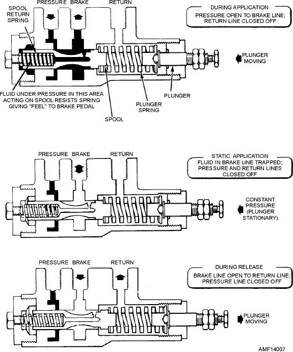
Figure 14-7.--Power brake control valve (sliding spool type).
Maintenance of the sliding spool brake control
power brake control valves. These units are generally
valve is limited to checking the action of the plunger.
used on aircraft equipped with a high-pressure
This is done by manually depressing the plunger until
hydraulic system and low-pressure brakes. The
it bottoms, and then releasing it suddenly. If the
purpose of the brake debooster cylinder is to reduce the
plunger remains depressed (does not snap out), the
pressure to the brake and increase the volume of fluid
valve is binding at the spool and sleeve. If binding
flow. Figure 14-8 shows a typical debooster cylinder
occurs, the valve should be replaced. Disassembly of
installation. The unit is being mounted on the landing
the valve is not permitted at the organizational level of
gear shock strut in the line between the control valve
maintenance, but may be performed by an intermediate
and the brake. The schematic diagram in the
or higher level activity.
illustration shows the internal parts of the cylinder.
When the brake is applied, fluid under pressure
Brake Debooster Cylinder
enters the inlet port to act on the small end of the piston.
The ball check prevents the fluid from passing through
In some power brake control valve systems,
the shaft. Force is transmitted through the small end of
debooster cylinders are used in conjunction with the
14-6