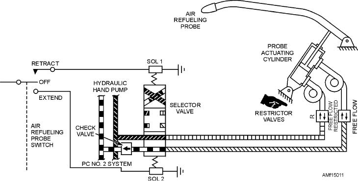
in figure 15-11 consists of the refueling probe,
the piston is fully retracted, locking fingers on the
refueling nozzle, a self-locking, two-position probe
piston lock the actuator and launch bar in the retracted
actuating cylinder, a lock swivel joint, two restrictor
position.
valves, a selector valve, and associated electrical
Hydraulic retraction of the launch bar is obtained
switches and relays.
by holding the launch bar control switch in RETRACT.
With the engines operating or external electrical
This action completes an electrical circuit to energize
and hydraulic power applied, the probe is extended by
the launch bar selector valve retract solenoid (solenoid
placing the refueling probe switch in the EXTEND
B). The energized selector valve directs hydraulic
position. This electrically actuates the solenoid selector
pressure to retract the launch bar actuator. The actuator
valve to supply restricted hydraulic flow to the extend
retracts, pulling the launch bar up and locking the
port of the probe-actuating cylinder. The restrictor
actuator and launch bar in the retracted position.
valves control the rate of cylinder extension and
Q15-13. What system eliminates the necessity for
retraction. The check valve prevents pressure surges in
flight deck personnel to manually connect an
the hydraulic return system from unlocking the
aircraft to the ships catapult harnesses?
probe-actuating cylinder during flight.
Q15-14. What accessories are included for the
After disengaging the probe nozzle from the tanker
catapulting launching system?
drogue, hold the air refueling switch in RETRACT to
Q15-15. What device on each side of the launch bar
actuate the solenoid selector valve to supply pressure to
shank raises the launch bar to the retracted
the retract port of the probe actuating cylinder, causing
position if automatic hydraulic retraction
it to retract and lock the probe into place. A cockpit
fails?
advisory panel transit light goes out whenever the probe
is locked in the extended or retracted position. A probe
floodlight, which illuminates the probe tip for visual
IN-FLIGHT REFUELING SYSTEMS
contact with the refueling drogue at night, is on
LEARNING OBJECTIVE: Identify the
whenever the refueling probe switch is in EXTEND
types of in-flight refueling systems. Identify
and exterior lights are on. The floodlight goes out when
their components and applicable maintenance
the refueling probe switch is placed in RETRACT or
requirements.
OFF. Organizational maintenance of the air refueling
probe system normally consists of operational checks,
Air refueling systems permit complete in-flight or
troubleshooting, rigging and adjusting, and removal
on the ground refueling of the aircraft fuel system. The
and installation of components.
refueling probe extension and retraction system shown
Figure 15-11.--Air refueling probe hydraulic system.
15-12

