The system adjusts the bypass bellmouth ring
ramp is positioned by the hydraulic actuator. The
position to maintain a preselected inlet airspeed and
actuator is controlled by the electrically operated
stable mass airflow through the inlet duct throughout
torque motor in the hydraulic servo valve.
the flight range of the aircraft. Movement of the
Movement of the aft ramp positions the perforated
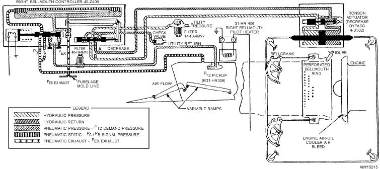
bellmouth ring also controls the amount of secondary
ramp through mechanical linkage. The position of
air bypassed around the engine for cooling. The valves
ramps is automatically selected through the ramp
in the bellmouth controller (fig. 15-15) are positioned
system by a temperature signal from the air data
by the inlet duct pressure differential and, in turn, direct
computer set. The ramp actuator is a double-acting
hydraulic pressure to the bellmouth ring actuator,
cylinder attached to the ramp linkage in such a way as
increasing or decreasing the bypass opening. The holes
to be free floating. This arrangement causes equal
drilled in the bypass ring assure cooling air to the
action on the linkages attached to each end of the
engine compartment when the ring is in the closed
cylinder.
position.
Figure 15-14 shows the complete hydraulic portion
Auxiliary air doors (not shown in fig. 15-15) open
of the variable ramp system, showing the actuator
to supplement the bellmouth bypass system at low
extending. Actuating the torque motor armature
airspeeds and during ground operation to prevent
positions the flapper valve in the servo valve, initiating
overtemperature and/or reverse airflow in the engine
the proper servo action to extend, retract, or hold the
compartment. These doors are located on the underside
actuator in position. As the actuator moves, it positions
of the fuselage and open in flight, at high speeds, as
the ramp through its mechanical linkage.
required to prevent excessive air pressure differential
Electrical components in the circuit translate an
between the engine compartment and outside ambient.
electrical signal, proportional to the ramp movement, to
The auxiliary doors are held closed by hydraulic
balance the amplifier circuits and hold the servo and
actuators, which are sized, to develop a force equivalent
ramp at this designated position until a new temperature
to the door area times the designated differential
signal initiates a change. If electrical or hydraulic
pressure. When the pressure limit is exceeded, the door
power failure occurs, air loads on the ramps will tend to
is pushed open (varying amounts) to keep the engine
cause the ramps to move toward the retract position.
compartment pressure from becoming excessive. As
The variable bypass bellmouth system monitors the
the engine compartment pressure is lowered, the
inlet duct operation and indicates any corrective action,
hydraulic actuators will pull the doors closed.
bypassing more or less of the airflow at the engine face,
The variable ramp, bellmouth bypass, and auxiliary
as shown in figure 15-15.
air door systems are powered by the utility hydraulic
Figure 15-15.--Variable bellmouth system.
15-17

