
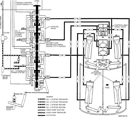
The cylinders for the left door are powered by the
system. Malfunctions in these systems will normally
No. 1 hydraulic system, and the cylinders for the right
require personnel of the AE, AD, and AM ratings
door are powered by the No. 2 hydraulic system. The
working together to operationally test the system and
main actuating levers are linked together so that in the
provide proper corrective maintenance.
event one system fails, the other will be capable of
Q15-22. What systems decrease engine inlet air
operating both doors. An unlock mechanism is
velocity to a subsonic flow with maximum
incorporated in the forward linkage to secure the doors
pressure energy and provide for the re-
when hydraulic power is removed. A hand pump
flection and bypass of surplus air not
system provides for emergency opening and closing of
required by the engine with a minimum of
the doors in the event both hydraulic and electrical
drag?
systems fail. Shutoff valves are provided within each
Q15-23. What component controls the amount of
normal system and the emergency hand pump system to
secondary air bypassed around the engine for
isolate the system. Two flow regulators are located
cooling?
upstream of the selector valve (dual system door
control valve).
BOMB BAY SYSTEM
The control valve has three positions--DOORS
OPEN, NEUTRAL, and DOORS CLOSED. In the
LEARNING OBJECTIVES: Identify the
DOORS OPEN position, fluid is ported to the dual
types of bomb bay systems. Identify their
controllable check valve, which bypasses pressure to
components and applicable maintenance re-
the opening side of the uplock mechanism cylinder. As
quirements.
the cylinder retracts, it unlocks the mechanical uplocks,
The bomb bay system is shown in figure 15-16. The
and then unseats the dual controllable check valve to
doors are actuated by mechanical linkage at each
port pressure to the open side of the door actuators.
end. Each door mechanism is powered by two
The control valve is normally operated by a
hydraulic-actuating cylinders.
two-position switch located on the pilot's armament
Figure 15-16.--Bomb bay door hydraulic schematic.
15-18