
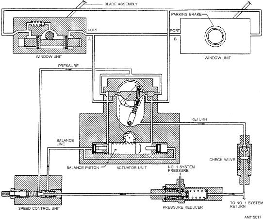
and a return line check valve. System pressure is
control panel. The switch energizes either pair of the
directed to the pressure reducer, where it is reduced to
four solenoids on the control valve to position the main
2,000 psi, and then the fluid passes to the speed control
spool to open or close the doors.
valve, which starts, stops, and controls the wiper blade
The uplock mechanism incorporates an overcenter
speed.
feature, which prevents the assembly from locking until
Hydraulic fluid is directed from the speed control
bearings on the doors trip the overcenter mechanism.
unit to the hydraulic actuator, which, in turn, controls
Limit switches on the uplock mechanism break the
and directs fluid to the window units. The actuator
electrical circuit to the control valve, and the
alternately allows fluid flow to opposite sides of the
spring-loaded valve returns to NEUTRAL. In this
window unit double piston. Constant speed of the wiper
position, all fluid is ported to the return lines, and the
blades is provided by fluid from the speed control valve
doors are held closed by the mechanical locks. The
and is directed to the balance pistons in the hydraulic
one-way restrictors installed in the open and close lines
actuator. Fluid is also directed to the window units
ensure smooth door operation and prevent cavitation of
through the hydraulic actuator normal inlet port. The
the door-actuating cylinders.
window units, by action of a rack and piston
Q15-24. How many positions does the door control
arrangement, convert the linear motion of the double
valve have in the bomb bay system?
piston to the reciprocating action of the drive shaft.
When the system has completed one wiper stroke
WINDSHIELD WIPER SYSTEM
and the hydraulic pressure at the window unit pistons
LEARNING OBJECTIVES: Recognize the
reaches a value equal to system pressure minus 200 psi,
windshield wiper system. Identify its compo-
the actuator will then reverse the flow to the opposite
nents and applicable maintenance require-
side of the window unit piston and repeat the wiper
ments.
stroke action in reverse.
The windshield wiper system shown in figure
Any obstruction on one windshield will stop that
15-17 consists of a pressure reducer, speed control
blade, but allow the other to continue until it completes
needle valve and drive mechanism, hydraulic actuator,
its stroke (or meets an obstruction), at which time the
two window actuator units and wiper blade assemblies,
pressure in the window units build up and the actuator
Figure 15-17.--Windshield wiper schematic.
15-19