which the fluid passes into the upper chamber during
Main Landing Gear
compression and returns during extension of the strut.
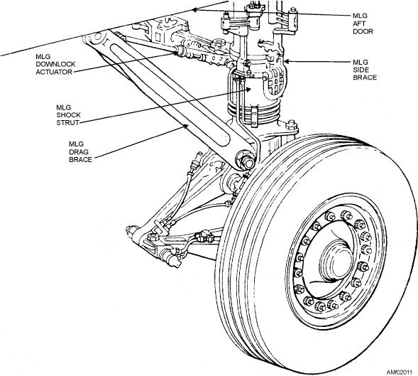
A main landing gear assembly is shown in figure
The size of the orifice is controlled by the up-and-down
2-11. The major components of the assembly are the
movement of the tapered metering pin.
shock strut, tire, tube, wheel, brake assembly, retracting
Whenever a load is placed on the strut because of
and extending mechanism, side brace, downlock
the landing or taxiing of the aircraft, compression of the
actuator, and drag braces. Tires, tubes, and wheels are
two strut halves starts. The piston (to which wheel and
discussed in another chapter of this nonresident
axle are attached) forces fluid through the orifice into
training course.
the cylinder and compresses the air or nitrogen above it.
The shock strut absorbs the shock that otherwise
When the strut has made a stroke to absorb the
would be sustained by the airframe structure during
energy of the impact, the air or nitrogen at the top
takeoff, taxiing, and landing. The air-oil shock strut is
expands and forces the fluid back into the lower
used on all Navy aircraft. This type of strut is composed
chamber. The slow metering of the fluid acts as a
essentially of two telescoping cylinders filled with
snubber to prevent rebounds. Instructions for the
hydraulic fluid and compressed air or nitrogen. Figure
servicing of shock struts with hydraulic fluid and
2-12 shows the internal construction of a shock strut.
compressed air or nitrogen are contained on an
instruction plate attached to the strut, as well as in the
The telescoping cylinders, known as cylinder and
maintenance instruction manual (MIM) for the type of
piston, form an upper and lower chamber for the
aircraft involved. The shock absorbing qualities of a
movement of the fluid. The lower chamber (piston) is
shock strut depends on the proper servicing of the
always filled with fluid, while the upper chamber
shock strut with compressed or nitrogen and the proper
(cylinder) contains the compressed air or nitrogen. An
amount of fluid.
orifice is placed between the two chambers through
Figure 2-11.--Main landing gear.
2-12

