
nitrogen), mechanical, or gravity systems, or a
combination of these systems.
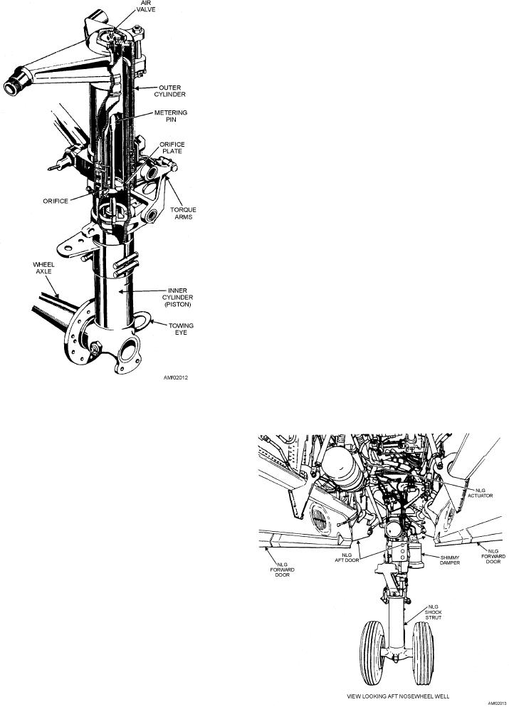
Nose Gear
A typical nose gear assembly is shown in figure
2-13. Major components of the assembly include a
shock strut, drag struts, a retracting mechanism,
wheels, and a shimmy damper.
The nose gear shock strut, drag struts, and
retracting mechanism are similar to those described for
the main landing gear. The shimmy damper is a
self-contained hydraulic unit that resists sudden
twisting loads applied to the nosewheel during ground
operation, but permits slow turning of the wheel. The
primary purpose of the shimmy damper is to prevent the
nosewheel from shimmying (extremely fast left-right
oscillations) during takeoff and landing. This is
accomplished by the metering of hydraulic fluid
through a small orifice between two cylinders or
chambers.
Most aircraft are equipped with steerable
nosewheels and do not require a separate self-contained
shimmy damper. In such cases, the steering mechanism
is hydraulically controlled and incorporates two
spring-loaded hydraulic steering cylinders that, in
addition to serving as a steering mechanism,
Figure 2-12.--Shock strut showing internal construction.
automatically subdue shimmy and center the
nosewheel.
RETRACTING MECHANISMS.--Some air-
craft have electrically actuated landing gear, but most
are hydraulically actuated. Figure 2-11 shows a
retracting mechanism that is hydraulically actuated.
The landing gear control handle in the cockpit allows
the landing gear to be retracted or extended by directing
hydraulic fluid under pressure to the actuating cylinder.
The locks hold the gear in the desired position, and the
safety switch prevents accidental retracting of the gear
when the aircraft is resting on its wheels.
A position indicator on the instrument panel
indicates the position of the landing gear to the pilot.
The position indicator is operated by the
position-indicating switches mounted on the UP and
DOWN locks of each landing gear.
EMERGENCY EXTENSION.--Methods of
extending the landing gear in the event of normal
system failure vary with different models of aircraft.
Most aircraft use an emergency hydraulic system.
Some aircraft use pneumatic (compressed air or
Figure 2-13.--Nose gear assembly.
2-13