
Figure 6-3.--Magnetic field surrounding an electrical
conductor.
Figure 6-5.--Creating a circular magnetic field in a part.
parts. It is also used for the detection of longitudinal
discontinuities, which lie in the same direction as the
current flow either in a part or in a part that a central
conductor passes through.
Circular magnetization derives its name from the
fact that a circular magnetic field always surrounds a
conductor, such as a wire or a bar carrying an electric
current (fig. 6-3). The direction of the magnetic lines of
force (magnetic field) is always at right angles to the
direction of the magnetizing current. An easy way to
remember the direction of magnetic lines of force
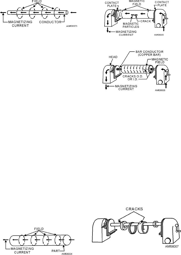
Figure 6-6.--Using a central conductor to circularly
around a conductor is to imagine that you are grasping
magnetize a cylinder.
the conductor with your hand so that the extended
thumb points parallel to the electric current flow. The
On parts that are hollow or tubelike, the inside
fingers then point in the direction of the magnetic lines
surfaces are as important to inspect as the outside.
of force. Conversely, if the fingers point in the direction
When such parts are circularly magnetized by passing
of current flow, the extended thumb points in the
the magnetizing current through the part, the magnetic
direction of the magnetic lines of force.
field on the inside surface is negligible. Since there is a
magnetic field surrounding the conductor of an electric
Since a magnetic part is in effect a large conductor,
current, it is possible to induce a satisfactory magnetic
electric current passing through this part creates a
field by placing the part on a copper bar or other
magnetic field in the same manner as with a small
conductor. This situation is illustrated in figures 6-6 and
conductor (fig. 6-4). The magnetic lines of force are at
6-7. Passing current through the bar induces a magnetic
right angles to the direction of the current as before.
field on both the inside and outside surfaces.
This type of magnetization is called "circular
magnetization" because the lines of force, which
LONGITUDINAL M AG N E T I Z AT I O N . --
represent the direction of the magnetic field, are
Longitudinal magnetization is used for the detection of
circular within the part.
circumferential discontinuities, which lie in a direction
transverse to or at approximately right angles to a parts
To create or induce a circular field in a part with
axis. Electric current is used to create a longitudinal
stationary magnetic particle inspection equipment, the
magnetic field in a piece of magnetic material. When a
part is clamped between the contact plates and current
part of magnetic material is placed inside a coil, as
is passed through the part, as indicated in figure 6-5.
This sets up a circular magnetic field in the part that
creates poles on either side of any crack or
discontinuity that runs parallel to the length of the part.
The poles will attract magnetic particles, forming an
indication of the discontinuity.
Figure 6-7.--Using a central conductor to circularly
magnetize ringlike parts.
Figure 6-4.--Magnetic field in part used as a conductor.
6-7