
Figure 9-1.--Insertion of can into Hydraulic Servicing Unit H-250-1.
contamination-free means of stowing the discharge
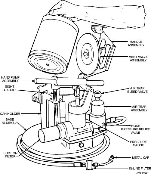
of the reservoir. It reads from 0 to 2 gallons, in
end of the service hose when the equipment is not in
1/4-gallon increments. An indicated level of 2 gallons
actual use.
or less means that the 1-gallon container is empty and
can be removed for replacement. A capped deaeration
Model HSU-1 Fluid Service Unit
port is located on top of the reservoir to permit bleeding
the air from the pump and output hose.
The Model HSU-1 fluid service unit (fig. 9-2) is
Can holder and handle assemblies are mounted
operated similarly to the H-250-1 unit, except that it
above the 2-gallon reservoir. The can holder positions
has a fluid-holding capacity of 3 gallons. Like the
the installed 1-gallon fluid container directly above the
H-250-1 servicing unit, the HSU-1 accepts a standard
reservoir, and also provides a means of placing the
1-gallon container and uses it as a fluid reservoir.
handle assembly over the container top. The handle
Additionally, it contains an integral 2-gallon reservoir
assembly is hinged to a bracket on the can holder
assembly. It has 3-micron filtration incorporated to
assembly. It is provided with a spring-loaded latch to
ensure delivery of contamination-free fluid.
lock the handle in the closed position. In addition to
The integral 2-gallon reservoir assembly is made
the carrying handle itself, the handle assembly
of anodized cast aluminum and (along with a hand
contains an upper can piercer, a vent check valve, and a
pump assembly) is mounted to a cast aluminum base.
filter. A vent hose is connected between the top of the
The lower can piercer is mounted on top of the
reservoir (sight gauge) and the upper can piercer.
reservoir and allows fluid to flow from the installed
Fluid is delivered by a single-action, piston hand
1-gallon container into the reservoir, automatically
pump that displaces 1.5 fluid ounces per full stroke at 0
replenishing it. A sight gauge indicates the fluid level
9-2