engages in a groove in a gas-operated piston installed in
and prevents the delay mechanisms from operating. As
a housing attached to the lower part of the unit body.
altitude decreases, the capsule peg retracts and allows
The piston is held in position by a frangible disc.
the mechanism to function.
When the RH multipurpose initiator cartridge fires
IMPULSE CARTRIDGE.--The impulse car-
during ejection, gas pressure from the cartridge enters
tridge CCU-102/A consists of a cylindrical brass body
the piston housing and moves the piston upwards,
containing two output charge chambers separated by a
rupturing the frangible disc and allowing the ratchet to
central connecting gas gallery. The upper end of the
pivot clear of the rack assembly's slotted end. When the
cartridge has two electrical igniters and is electrically
altitude is low enough that the barostat is not restraining
initiated by signals from the electronic sequencer--a
the mechanism, the rack assembly will rise under the
primary signal to initiate the cartridge and a backup
action of its spring, governed by the delay mechanism.
signal through the second connector to provide system
After the delay has elapsed, the rack disengages from
redundancy. The lower end is initiated by the delay
the gear train and the firing pin rises rapidly to strike the
mechanism firing pin striking the percussion cap.
cartridge. If the cartridge has not previously been fired
Output charge initiated at either end will crossfire, via
electrically by the sequencer, the gas produced by the
the gas gallery, to ignite the output charge in the other
cartridge passes out of the BRU to operate the upper
chamber. The resultant gas pressure is discharged from
and lower harness locks along with the secondary
the center of the cartridge into an annular groove via gas
cartridge in the parachute deployment rocket motor.
ports spaced evenly around the central gas gallery.
TIME-DELAY MECHANISM.--The time-delay
Shoulder Harness Reel
mechanism consists of a spring-loaded rack assembly
in mesh with a gear train controlled by an escapement.
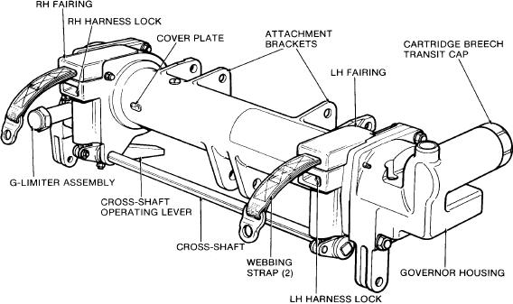
The shoulder harness reel (fig. 2-16) is fitted
The gear train consists of a primary spur and gear, a
horizontally across the front faces of the main beams
secondary spur and gear, an idler wheel, a release
and serves as a center cross-beam for the main beams
wheel, and a release rocker.
assembly as well as a means of securing the upper
harness. It ensures the occupant will be correctly
The rack assembly consists of a rack end screwed
positioned and locked in for ejection. It permits the seat
into a slotted end. The two components are secured
occupant to lean forward and twist around in the seat
together with a locking screw. The upper end of the rack
for maximum visibility, but restrains forward
end is shaped to form a firing pin.
movement in the event of excessive forward
To retain the rack in the cocked position, one face
deceleration. For normal flight operations the shoulder
of a ratchet in the bottom housing engages in the slotted
harness is free to extend and retract as the occupant
end of the rack assembly. Another face of the ratchet
moves in the ejection seat. The shoulder harness control
Figure 2-16.--Shoulder harness reel.
2-15

