Two leg restraint line snubbers, each with a leg
(fig. 2-19) ensure that the correct rocket motor is
restraint line, are attached to the front face of the seat
installed. A gas pipe to the rocket motor firing
bucket. Pulling inboard on the fabric loops attached to
mechanism is connected to a trombone tube on the LH
the release plungers on the inboard side of each snubber
rear of the seat bucket. The trombone tubes on the rear
will release them to adjust the leg lines. The leg
of the seat bucket connect to ballistic manifolds
restraint lines taper plugs are secured in locks
mounted on the main beams. Connections are a push fit
positioned on the seat bucket side plates.
secured by key operated quick-release pins, gas
integrity being maintained by O-ring seals.
Seat Height Actuator
Leg Restraint System
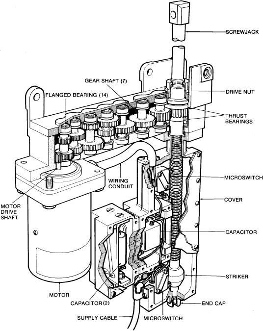
The seat height actuator (fig. 2-21) adjusts the seat
bucket vertically in relation to the seat beams. The
The lower harness locks and release mechanism are
assembly consists of a vertical electric motor and
within the lower rear corners of the seat bucket
housing assembly connected by a transverse gearbox
(fig. 2-20). Halfway up the inner face of the seat bucket
assembly to the upper end of a screwjack housing.
sides are sticker clips. The pin puller is mounted at the
rear of the seat bucket on the lower right hand side.
Figure 2-21.--Seat height actuator (SJU-17(V)3/A and 4/A).
2-19

