
ELECTRICAL
CONTROL
BOX HARNESS
START
COUNTER
ELECTRICAL
ACCESSORY
EXTERNAL
RECEPTACLE
ELECTRICAL
SOURCE
RECEPTACLE
HIGH VOLTAGE
IGNITION UNIT
TERMINAL
BOARD
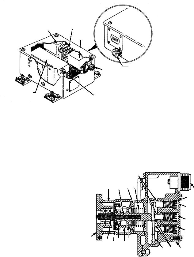
ASf12009
Figure 12-9.--Electrical control box.
The first to operate is the 35-percent switch, which
caution must be observed when maintenance is
de-energizes the starter and ignition holding relay. The
performed on the ignition system. Always make
second to operate is the 95-percent switch, which
certain that the capacitors are fully discharged before
energizes the ready-to-load light, load switch circuit,
removing or checking components of the ignition
and the start counter. The last switch to operate, the
system.
110-percent switch, operates at 110 percent and is a
GENERATOR.--The generator, driven by the
safety device to protect the engine from overspeed.
accessory drive gear section, is a continuous-duty unit
rated at 12 amperes and 28 volts. Cooling of the
5
generator is provided by air drawn through cooling
inlet holes in the generator housing, through the
4
3
1
2
generator, into a cooling outlet tube, and into the
6
turbine exhaust. Control of the generator and the
7
circuits associated with it is the function of the voltage
regulator and reverse current relay. These units and a
8
noise filter are located in the generator control panel.
9
STARTER MOTOR ASSEMBLY.--The starter
unit operates on a 24- to 28-volt power supply; power
10
for operation of the starter may be provided by a
19
battery or may be supplied from an alternate external
18 17 16 14
15
28-volt source. The starter is provided with a clutch
13 12
11
m e c h a n i s m , w h i c h a l l ow s a u t o m a t i c i n i t i a l
ASf12010
engagement, and disengagement is accomplished
when the speed of the accessory drive is exceeded.
1.
Housing
11.
Switch cover
2.
Centrifugal switch shaft
12.
Leaf spring
Starter motor current is cut off at 35 percent of engine
3.
Spring sliding retainer
13.
Switch actuating lever
speed.
4.
Compression spring
14.
Lever actuator
5.
Push rod
15.
Governor flyweights
CENTRIFUGAL SWITCH ASSEMBLY.--
6.
Receptacle
16.
Ball bearing
The centrifugal switch assembly (fig. 12-10), through
7.
Access plate
17.
Fulcrum flyweights
the operation of a set of flyweights, controls the
8.
Adjusting screw
18.
Overspeed switch bearing carrier
9.
Adjusting screw
19.
Mounting flange
sequence of operation of the electrical system. As the
10.
Adjusting screw
flyweights are caused to move outward by centrifugal
Figure 12-10.--Centrifugal switch assembly.
force, three switches are actuated by an actuating lever.
12-10