
1
34
6
9
5
7
8
11
2
10
12
13
15
16
14
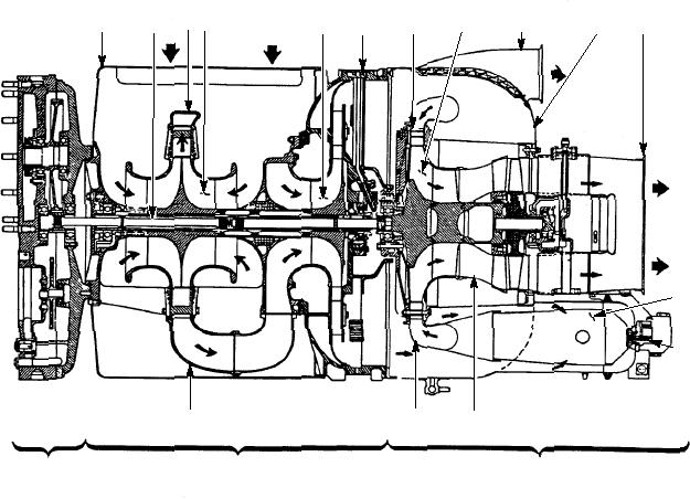
ASf12013
ACCESSORY
COMPRESSOR
TURBINE
DRIVE SECTION
SECTION
SECTION
Compressor plenum assembly
9. Bleed-air outlet duct
1.
Torsion shaft
2.
10. Turbine plenum assembly
Crossover duct
11. Turbine exhaust duct
3.
Compressor first stage impeller
12. Combustion chamber
4.
Compressor second stage impeller
13. Fuel atomizer assembly
5.
14. Turbine nozzle and shroud assembly
6.
Compressor oil jet assembly
7.
15. Combustion collector manifold assembly
Turbine radial nozzle assembly
16. Crossover duct
8.
Turbine radial wheel and shaft assembly
Figure 12-13.--Engine airflow schematic.
A starter (9) mounted on the right front of the
that mounts on the front end of the compressor section.
A torsion shaft, driven by the compressor rotating
accessory case
assembly, is coupled to and drives the main pinion
A start-counter assembly (8) mounted in a
gear. Through various reduction gears, the pinion gear
provides output drives for the fuel control, oil pump,
bracket on the right side of the accessory case
centrifugal switch, and the power output shaft. An
An ignition unit (16) and a two-stage oil pressure
input drive and gearing is provided for the electrical
engine starter.
switch (22) mounted on the left side of the
accessory case
ENGINE FURNISHED ACCESSORIES.--
The accessories (as viewed from the exhaust) are part
A pneumatic shutoff valve (21) located on the
of the gas turbine engine (fig. 12-14) and include the
bottom left rear of the turbine plenum
following:
A fuel control (23) mounted on the left front of
A fuel shutoff and drain solenoid valve (14)
the accessory case
located at the bottom rear of the turbine
assembly
An oil pump (12) mounted on the front bottom of
the accessory case
Two pneumatic thermostats (19 & 20) located in
A three-speed centrifugal switch (10) mounted
the turbine exhaust duct area (only one on the
on the lower right front of the accessory case
GTC-100-82 model)
12-15