
1 2
3
5
6
7
8
14
12
11
13
4 10
9
15
16
17
18
19
20
23
22
21
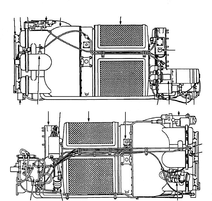
ASf12014
10.
Centrifugal switch assembly
18. Pressure tap
1.
Atomizer assembly
11.
19. Thermostat (acceleration and
2.
Cap assembly
overtemp)
12.
Oil pump assembly
3.
Combustion chamber
20. Igniter plug on #5 combustion
13.
Thermostat (load control)
4.
Modulating and shutoff valve
chamber
14.
Shutoff and drain solenoid valve
5.
Bleed-airdct
21. Valve (pneumatic shutoff, air
6.
Turbine section
assembly (fuel)
scheduling)
7.
Compressor section
15. Accessory assembly
22. Oil pressure switch
8.
Start counter
16. Ignition unit
23. Fuel (metering) control assembly
9.
Starter motor assembly
17. Compressor air inlet screen
Figure 12-14.--Right and left view of a gas turbine engine.
Six fuel atomizer assemblies (1) attached to the
ENCLOSURE P ROV I D E D AC C E S S O R -
IES.--A temperature-regulated oil cooler, vane axial
combustion cap assemblies at the rear of the
oil cooler fan and ducting, an oil tank, as well as a
engine
primary fuel filter with shutoff, a fuel boost pump, and
A modulating and shutoff valve (4) mounted on
the related supply/return lines are located within the
the top rear of the turbine plenum
enclosure assembly. In addition, the turbine control
12-16