
5
7
6
1
8
9
4
15
11
10
12
2
16
13
14
3
18
19
20
17
21
33
23
22
24
28
27
26
25
29
ASf12016
30
32
31
HIGH
FUEL
LOW
PRESSURE
DRAIN
PRESSURE
FUEL
FUEL
CONTROL
PRE-SET ORIFICE
AIR
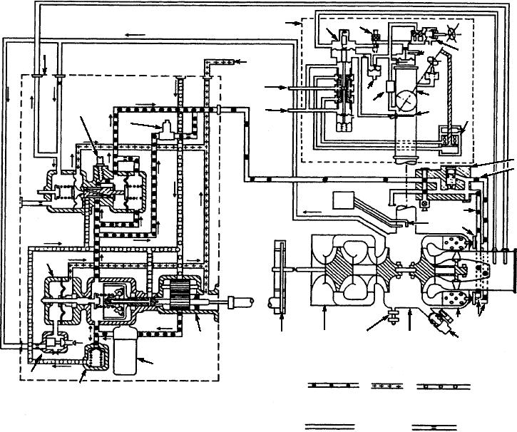
1.
Fuel contrl
12. Control air filter
23. Combustion chamber
2.
Fuel scheduling valve
13. Inlet air thermostat
24. Pneumatic air valve (scheduling)
3.
Auxiliary fuel solenoid valve
14. Valve actuator
25. Turbine section
4.
Fuel leakage drain
15. Servo pressure oil in
26. Turbine plenum drain valve
5.
Modulating and shutoff valve
16. Servo scavenge oil out
27. Compressor section
6.
Hydraulic piston servo assembly
17. Pressure-differential probe
28. Accessory drive section
7.
Valve actuating solenoid valve
18. Shutoff and drain solenoid valve
29. Fuel pump
8.
Rate head
19. Secondary pressure fuel line
30. Fuel filter
9.
Variable pressure regulator
20. Primary pressure fuel line
31. Relief valve
10.
Bleed-air outlet
21. Fuel atomizer assembly
32. Two speed valve
11.
Pressure regulator
22. Fuel manifold
33. Governor
Figure 12-16.--Engine fuel and control air system and bleed-air system schematic for typical GTCP-100.
Air System
When the output air switch is selected for lower
engine speed operation, the circuit to the
The air system consists of bleed-air control
air-pressure-ratio solenoid valve in the fuel control
components, surge control components, pneumatic
de-energizes to allow the solenoid to open and bleed
control components, and the necessary
off some of the control air acting on the mechanical
interconnecting plumbing. The main component for
governor diaphragm. This reduction in applied control
bleed-air control is the modulating and shutoff valve
air resets the mechanical governor's spring tension for
(load control valve) (fig. 12-18), which incorporates
a lower engine speed, preset at 80 percent by the
within one unit a butterfly shutoff valve, fixed and
low-speed adjustment screw.
variable pressure regulators, an inlet air thermostat, an
12-19