
assemblies, as well as any needed clamps, brackets,
DRIVE
GEAR
and mounting hardware. The main component of the
PUMP
system is the three-speed centrifugal switch (fig.
HOUSING
12-21). It contains three centrifugally actuated
switches for controlling the sequence of engine
SCAVENGE
OIL INLET
operation. Other components of the system, shown in
FILTER
figure 12-22, are the electrical starter, the control relay,
HOUSING
MANIFOLD
the ignition unit, the igniter plug, the thermocouple,
FITTING
the oil pressure switch, and the start counter.
The system provides the required electrical
TEMPERATURE BULB
starting and control operations through the entire range
OR SWITCH FITTING
of engine operation. A master switch supplies 24 volts
PRESSURE REGULATOR
OIL INLET
CONTROL VALVE
of dc battery power to the engine electrical system.
Upon actuation of the start switch, the electrical starter
EXTERNAL VIEW
motor rotates the engine (through a sprague clutch)
until the engine reaches 35 percent of the governed
FILTER RELIEF VALVE
PUMP
speed; at this time, the centrifugal switch cuts out the
FILTER
starter circuit.
The oil pressure switch contact sets close
sequentially and activate the ignition unit. Then, the
contacts actuate the fuel shutoff and drain solenoid
valve and the start counter.
The ignition unit provides pulsed, high voltage to
the igniter plug until the centrifugal switch cuts out the
ignition circuit at 35 percent of governed speed; at this
speed, combustion is self-sustaining. The load light is
OIL PRESSURE
energized by the centrifugal switch at 95 percent of
REGULATOR
VALVE
PRESSURE
governed speed to indicate the engine is operating at
OIL IN
ADJUST
OIL INLET
sufficient speed to provide bleed air.
SCREW
MANIFOLD
FITTING
FITTING
ASf12020
The centrifugal switch cuts out all circuits and
shuts down the engine at 110 percent of engine
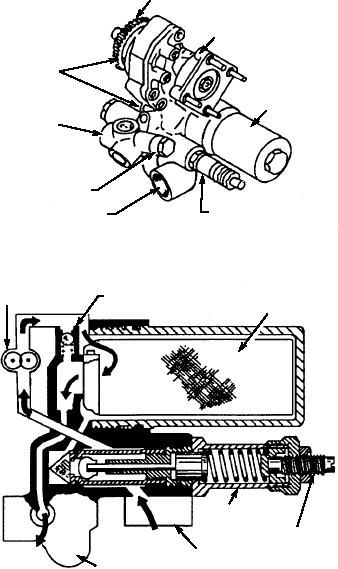
OIL PUMP SCHEMATIC
governed speed by eliminating the ground to the
Figure 12-20.--Oil pump assembly.
electrical system holding coil within the control relay.
to mix metered, cooled oil with hot oil, and to cool the
JET AIRCRAFT START UNIT, MODEL
hot oil to operating temperature. The relief valve
A/M47A-4
allows oil to bypass the cooler if pressure increases due
to a failed valve or clogged cooler.
The Model A/M47A-4 jet aircraft start unit (shown
in figs. 12-23 and 12-24) is a complete, self-contained
OIL DRAIN PLUG.--The oil drain plug is
unit that consists of a GTCP-100 gas turbine engine
located at the bottom of the oil tank. The plug allows
mounted in a flyaway assembly enclosed in a
the oil tank to be completely drained of all old or
skid-mounted, weather-resistant enclosure. Some
contaminated oil. This drain plug is accessible through
models of the A/M47A-4 are mounted on trailers for
an enclosure access door. It is important that you
ease of movement from aircraft to aircraft or place to
remember to replace the oil filter element after
place. The A/M47A-4 supplies compressed air at two
completely draining the oil tank and before reservicing
pressure ratios, 5:1 and 3.6:1, for aircraft engine
the tank with fresh oil.
starting and for ac and dc electrical power for operating
aircraft with ac and dc electrical components. The
Electrical System
A/M47A-4 is primarily a shore-based unit; however,
some are used on carriers for maintenance of jet
The electrical system consists of electrical
components, wiring harness assemblies, and lead
engines.
12-24