
Also, if oil pressure is lost during operation, this switch
ELECTRICAL CONTROL BOX.--Electrical
control of the engine is maintained through the
functions to shut down the engine. Sometimes, the oil
electrical control box (fig. 12-9). It houses the starter
pump requires priming to provide oil pressure at the
and ignition holding relay, fuel holding relay, ignition
time of starting. The oil drain solenoid valve drains
unit, and the start counter. The starter and ignition
excess oil from the accessory section during engine
holding relay and the fuel holding relay, when
deceleration.
energized, provide power to the circuits they control
and also to their own coils for a holding action. The
Electrical System
ignition unit provides the high-tension current to the
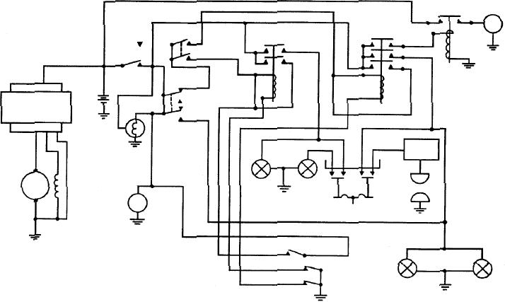
The electrical system provides the means for
igniter plug.
starting, operating, and stopping the engine. It is a
IGNITION SYSTEM.--The gas turbine engine
26 2-volt dc system, which may be operated from
ignition system is very simple in construction and
a battery or an external power source, such as a
operation. The entire system consists of the igniter
mobile electric power plant. The electrical system
(spark unit), which is located in the combustion
has two groups of components--engine mounted
chamber; a section of high-tension ignition lead; and
and enclosure mounted. The engine group is the
the ignition unit, which provides the high-energy
same for all installations, but the enclosure group
voltage source. This is accomplished by a step-up
varies as to type of components and circuitry. A
transformer, which charges internal storage capacitors.
typical electrical system schematic is shown in
The storage capacitors are then discharged across a
figure 12-8.
booster coil arrangement, and the high voltage is
applied to the igniter. After the engine has started and a
The components of the engine group are the
flame is established in the combustion chamber, the
electrical control box, the ignition system, the
ignition system is de-energized, since burning is
generator, the starter motor assembly, the centrifugal
constant once a successful start has been
switch assembly, the oil drain solenoid valve, the fuel
accomplished.
solenoid valve, the acceleration stabilizer solenoid and
adjustable orifice assembly, and the oil pressure
NOTE: The voltage to the igniter is dangerously
switch.
high (near 15,000 volts of pulsating dc); therefore,
MASTER
STARTER RELAY
STARTER
(STOP-RUN)
M
AND IGNITION
SWITCH
START
FUEL HOLDING
HOLDING RELAY
SWITCH
STOP
STARTER
RELAY
START
RUN
24V
BATTERY
A+ A- B+ B-
OFF
CONTROL
ON
PANEL
BLEED LOAD
ABCDE
SWITCH
LOAD
LIGHT
IGNITION
UNIT
DC
FUEL
IGNITER
OIL
SOLENOID
PLUG
SOLENOID
VALVE
DRAIN
START
OIL PRESSURE
VALVE
COUNTER
SWITCH
95% SWITCH
110% SWITCH
35% SWITCH
LOAD
ASf12008
CENTRIFUGAL
STABILIZER
VALVE
SWITCH
SOLENOID
SOLENOID
ASSEMBLY
Figure 12-8.--Electrical system.
12-9