
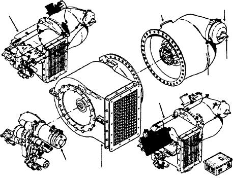
COMBUSTION
CHAMBER
CAP
TURBINE
PLUMBING
SECTION
SYSTEM
FUEL
ATOMIZER
PLUG
ELECTRICAL
SYSTEM
ACCESSORY
SECTION COMPRESSOR
SECTION
ASf12004
Figure 12-4.--Major sections of a gas turbine compressor (GTC-85).
Compressor Section
FUNCTIONAL SYSTEMS
This section provides a source of compressed air
Before you attempt to operate a gas turbine unit,
for combustion, cooling, and pneumatic power in the
you should have a knowledge of the different systems
form of bleed air.
and the function performed by each. In the gas turbine
unit there are four main functional systems, which are
The ambient air is moved by the first and second
listed as follows:
stage impellers, and is directed through diffusers that
Airflow
are mounted directly after the impellers. Compression
is accomplished by the diffusers due to their divergent
Fuel and bleed-air control system
shape.
Lubrication system
The impellers are mounted on a common shaft.
The ends of impellers are splined internally to receive
Electrical system
the drive shafts, which connect the compressor to the
accessory drive shaft and connect the turbine to the
Airflow
compressor.
In figure 12-5, note that the rotation of the
Power Turbine Section
compressor creates a low-pressure area at the inlet side
of the unit. This draws air through the oil cooler into the
The turbine section is the power section, which
first stage compressor plenum chamber (air supply
provides driving power for the entire unit. The major
chamber). Also note that the first stage of the
parts of this section are the turbine wheel, turbine
compressor is constructed with a dual-entry; this is
plenum, combustion chamber assembly, and nozzle
necessary to provide the large volume of air that is
a s s e m b l y. A i r, w h i c h h a s b e e n t a ke n i n t o t h e
required for engine combustion and cooling and for
compressor, is routed to the combustion chamber
supplying pneumatic power.
section where it is mixed with fuel and ignited. As the
fuel-air mixture is burned, the gases expand rapidly,
As air is drawn into the first stage of the
increasing the velocity of the gas as it is exhausted to
compressor, tremendous velocity is imparted to it by
the rear through the nozzle assembly. From the nozzle
the first stage impeller. The air is then directed into the
assembly, these hot gases are directed onto the blades
first stage diffuser, where it is slowed down and its
of the turbine wheel, turning the turbine at a very high
pressure increased (first stage compression) to
speed. In turn, the turbine drives the compressor and
approximately 18 psi. It is then directed through
the accessory drive assembly.
interstage ducts into the second stage of the
12-4