
PNEUMATIC POWER GAS TURBINE
level safe enough for turbine operation as it is expelled
ENGINE, MODEL GTC-85-72
through the exhaust.
T h e t u r b i n e r e c e ive s t h e h e a t e d ga s e s a n d
LEARNING OBJECTIVES: Identify the
transforms the energy of the burned gases to shaft
components of GTC-85-72 electrical, fuel,
power that drives the compressor and accessories. The
bleed air, and lubrication systems.
heat causes the compressed air to expand. The only
outlet from the combustion chamber is through the
This engine consists of a two-stage,
turbine. In its rush to escape, the gases build up enough
centrifugal-flow compressor directly coupled to a
ve l o c i t y t o t u r n t h e t u r b i n e . T h e t u r b i n e a n d
radial, inward-flow, single-stage turbine. There are
compressor are connected by a torsion shaft. The
several different configurations of the GTC-85-72 in
use. The major difference is the type of enclosure
accessory section operates by a gear reduction drive
installation used. The most common is the GTC-85
connected to the front of the compressor shaft.
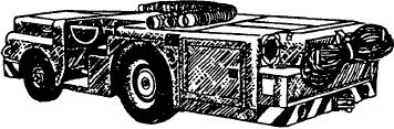
enclosure mounted at the rear of the A/S32A-31A
The compressed air is drawn off from the turbine
aircraft tow tractor (fig. 12-3).
plenum for use as pneumatic air. If all the air were
The gas turbine compressor takes air, compresses
routed to the turbine from the compressor, the turbine
it, adds fuel, ignites the mixture, and directs the
would produce more power than is needed to operate
expanded gas against a turbine. A large mass of air is
the compressor and accessories. Therefore, the amount
required by the gas turbine engine. The inlet must
taken for pneumatic equipment operation would not
supply as much as 10 times the amount of air required
reduce the desired output of the engine. (In a jet engine
by a reciprocating engine. The air must reach the
used in aircraft, where pneumatic air is not bled off,
compressor in a smooth flow free from turbulence.
this excess energy is used for propulsion.)
The function of the compressor is to increase the
MAJOR COMPONENTS
pressure of the air received from the entrance duct, and
then discharge it to the combustion chamber in the
The gas turbine engine, which is normally referred
quantity and at the pressure desired. The power to drive
to as a unit, consists of a two-stage centrifugal
the compressor is provided by the turbine. The turbine
and compressor units and their connecting shafts
compressor directly coupled to a radial inward-flow
comprise the rotating assembly. The rotating assembly
turbine wheel. Compressed air is obtained as bleed air
is the only major moving part in the gas turbine.
from the second stage of the compressor, which also
Because its motion is entirely rotary, operation is
supplies air to support fuel combustion in the turbine
inherently smooth.
section. The unit is composed of three main
sections--accessory, compressor, and power turbine
The combustion chamber serves to contain the
(fig. 12-4).
combustion process, which raises the temperature of
the air passing to the turbine. The combustion process
Accessory Section
injects fuel into the compressed air and ignites the
mixture. This process releases the potential energy
The accessory section is designed as a separate
contained in the fuel-air mixture. Approximately 30
assembly and consists of a gear reduction drive
percent of the air from the compressor combines with
coupled directly to the compressor shaft through a
the fuel mixture in the combustion process. The other
torsion shaft. The accessory housing mounts and
70 percent of the air is used for cooling at 100-percent
provides drives for the following accessories:
no load. The cooling air is mixed with the combustion
gases, which lowers the temperature of the gases to a
Starter
Centrifugal switch
Oil pump assembly
Fuel accessory assembly (fuel pump and control
ASf12003
Figure 12-3.--Tractor-mounted gas turbine enclosure.
unit)
12-3