
J
H
E
K
G
F
B
A
C
D
ASf02010
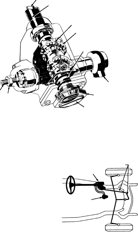
A.
Lash adjuster screw locknut
F.
Pitman arm
B.
Lash adjuster screw
G.
Worm
C.
Worm bearing adjusting screw locknut
H.
Jacket
D.
Worm bearing adjusting screw
J.
Streeing gear shaft
E.
Recirculating balls
K.
Ball nut
Figure 2-10.--Recirculating ball-type steering gear.
pitman shaft and arm. When the driver returns the
steering wheel to the neutral or straight ahead position,
CONVENTIONAL
STEERING LINKAGE
the pressure on both the right and left turn sides of the
POWER
piston is equalized, and the vehicle travels straight
STEERING UNIT
ahead. The pump is usually adjacent to a fluid reservoir
where the excess hydraulic fluid is stored. Figure 2-11
is a diagram of this type of system.
In the other type of power steering system, the
HYDRAULIC PUMP
control valve is on the pitman arm at the base of the
AND RESERVOIR
steering column. The power cylinder is mounted on the
tie rod between the wheels. In the system shown in
figure 2-12, the power cylinder is double acting. When
the steering wheel is turned, the pitman arm turns and
routes fluid under pressure to one side of the cylinder,
ASf02011
which assists in turning the wheels. When the steering
Figure 2-11.--Diagram of a power steering unit.
wheel is neutral, equal pressure is applied to both sides
of the power cylinder.
2-9