in manual steering. Because of this, wear of the
constructed so that to remove it from the vehicle, one
linkage will normally progress to a dangerous point
or both ends must be disassembled or loosened. The
before the operator typically becomes aware of the
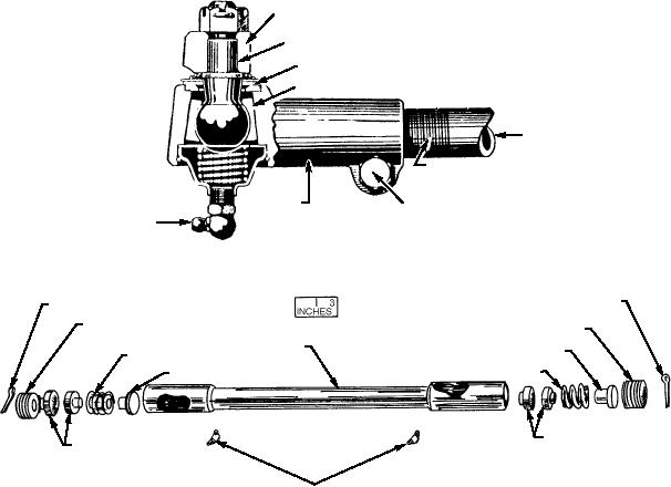
adjusting plug (fig. 2-19) is used to remove any free
problem.
play between the drag link and the connecting parts of
the linkage. Occasionally, adjustment of the plug is
Should hard steering occur, check the pressure
needed to compensate for wear of the ball and seats
of the steering pump to determine if that is the
or weakening of the spring.
problem. Use a suitable pressure gauge to determine
the pressure of the system. Follow the
The tie rod is equipped with a ball-type socket at
manufacturer's procedure, and compare the results
each end to allow for movement of the connecting
to the specifications in the technical manual. If
parts of the steering linkage. These sockets, called
within limits, adjust the pressure by altering spring
TIE ROD ENDS, must be checked for wear or slack.
tension in the relief valve. If the results are not within
The linkage should pivot at the ball socket without
limits and cannot be adjusted, a faulty component is
allowing free movement between the socket and
indicated, and it should be replaced.
ball. A slight drag is considered the optimum
condition of the ball joints. In addition to the flexible
Other Maintenance Procedures
end connections, the linkage is designed so that an
adjustment can be made when performing wheel
Lubrication involves the greasing and oiling that
alignment. The tie rod is normally connected
is performed at the time the entire vehicle is greased.
directly to the steering knuckle or spindle arm and
Figure 2-18 shows the tie rod end grease fitting.
used to transmit the steering effort to the wheel via
Consult the manufacturer's service instructions for
the knuckle or spindle.
the proper lubricant to use.
You can check worn or improperly adjusted
linkage connections by jacking up the front end of the
Depending on the steering arrangement, a drag
vehicle, grasping each wheel (front and rear of the
link or idler arm rod may be used in the linkage to
wheel), and moving the wheel in and out to check for
connect the pitman arm and the remainder of the
excessive movement. At the same time, you can check
steering linkage. This portion of the linkage is usually
KNUCKLE ARM
STUD
DUST SEAL
BALL SOCKET
TIE ROD
ADJUSTING
THREADS
TIE-ROD
END
CLAMP BOLT
LUBRICANT
FITTING
ASf02018
Figure 2-18.--Tie rod end showing clamp bolt and adjusting threads.
COTTER PIN
COTTER PIN
ADJUSTING PLUG
ADJUSTING PLUG
DRAG LINK
SPRING PLUG
SPRING
SPRING
SAFETY PLUG
BALL SEATS
BALL SEATS
ASf02019
LUBRICATION FITTINGS
Figure 2-19.--Drag link assembly--exploded view.
2-14

