limitations of the spring-loaded weight. The governor
pressures are used to control another valve, which, in
housing rotates with the output shaft. At no speed or
turn, controls a regulated pressure sufficient to operate
low speed, the spring is able to keep the valve
the servos and clutches. The valve controlled by the
positioned to prevent fluid flow or restrict it to a very
throttle and governor pressures is called a shift valve.
small amount. As vehicle speed increases, so does the
Shift Valve
centrifugal force acting on the weight. When sufficient
force acts on the weight, it moves outward against the
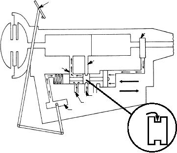
The shift valve, located in the hydraulic control
spring and allows more fluid flow (greater pressure).
unit, moves to up shift the transmission gear ratio when
As more pressure is built in the governor output line, it
governor pressure becomes greater than throttle
is also being built up between the spool lands of the
pressure. As shown in figure 2-69, with the shift valve
governor valve. The result is to position the valve by
in the up shift position, ports in the valve body are
spring pressure and pressure acting on the spool lands
(one larger than the other) to balance the centrifugal
uncovered, allowing oil from a regulated pressure
force acting on the weight.
source (normally line pressure) to pass unrestricted to
one or more of the operating units. Energizing one or
The fluid velocity governor consists of a pilot tube
more of the operating units causes a change in the
that is fixed (stationary), and usually sits between two
planetary gear ratio. By using throttle pressure
sets of vanes in an oil-filled drum. The oil drum (can) is
(reflecting engine speed), governor pressure
mounted on the transmission output shaft and rotates
(reflecting vehicle speed), and a shift valve to control
with it. The pilot tube is a small tube open at both ends
the operating units, gear shifting is automatic.
and curved on the end inserted into the oil. This tube
does not rotate with the oil drum. As the drum rotates,
T h e s h i f t va l ve s h ow n i n fi g . 2 - 6 9 i s a
its vanes propel the oil into the stationary curved pilot
spring-loaded, spool-type valve. It has two lands of
tube. The velocity of the oil entering the pilot tube is
equal area and one larger area land. When the
directly proportional to the speed of the output shaft.
transmission is in neutral (no hydraulic oil going to
Thus, it is capable of transmitting hydraulic pressure
any of the control units), the shift valve spring moves
sensitive to the vehicle speed.
the valve to the right, blocking the clutch port. This
means that the valve is always set so the vehicle will
The governor's oil pressure causes the upshifting
start forward in the low position of the shift valve,
of the transmission (higher gear ratio), but the throttle
and only up shift when governor pressure exceeds
valve pressure (fig. 2-66) opposes or delays the
throttle pressure. As the vehicle moves forward,
upshifting. However, the pressures from the throttle
governor pressure will be directed to the rear area of
and governor valves are not sufficient to operate the
servos and clutches effectively. Therefore, these
the large land in the shift valve. When the governor
ACCELERATOR
PEDAL
GOVERNOR
OPERATING
RANGE
UNITS
SECTION
CONVERTER
SERVO
CLUTCH
UPSHIFT
DOWNSHIFT
VENT
LINE PRESSURE
THROTTLE
VALVE
LAND
GROOVE
ASf02069
Figure 2-69.--Shift valve.
2-53

