
a very common condition found in transmissions, since
meshed with the ring gear; as they walk around the sun
speed reduction is desired in a reverse situation.
gear (while rotating) on their shafts, they force the ring
gear to rotate at a speed increase. Not all of the
There are two additional conditions. One
conditions shown in figure 2-60 are used in vehicle
condition is DIRECT DRIVE, whereby any two
transmissions, but they should be studied for full
members are locked together giving a drive ratio of 1 to
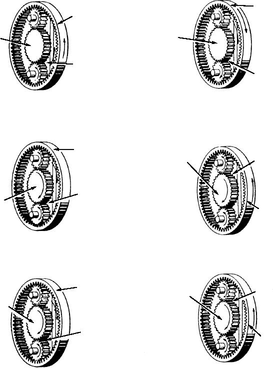
understanding of the planetary gear system. Figure
1. The other is NEUTRAL, whereby torque is simply
2-61 shows the six conditions referred to in fig. 2-60.
blocked because no member is held stationary (the
Notice condition 6 in both figures 2-60 and 2-61; this is
(1)
(2)
DRIVEN MEMBER
(INPUT)
DRIVEN MEMBER
(OUTPUT)
STATIONARY
STATIONARY
DRIVING MEMBER
(INPUT)
DRIVEN MEMBER
(OUTPUT)
LESS SPEED
MORE SPEED
MORE TORQUE
LESS TORQUE
(3)
(4)
STATIONARY
DRIVEN MEMBER
STATIONARY
(OUTPUT)
DRIVING
DRIVEN MEMBER
MEMBER
(OUTPUT)
(INPUT)
DRIVING MEMBER
(INPUT)
LESS SPEED
LESS SPEED
MORE TORQUE
MORE TORQUE
(6)
(5)
STATIONARY
DRIVING MEMBER
STATIONARY
DRIVEN
(INPUT)
MEMBER
(OUTPUT)
DRIVING MEMBER
DRIVEN MEMBER
(INPUT)
(OUTPUT)
LESS SPEED
MORE SPEED
ASf02061
MORE TORQUE
LESS TORQUE
Figure 2-61.--Views of six speed/torque ratios for a simple planetary gear system.
2-48