In some transmissions only one oil pump may be
used, and it is mounted at the front of the transmission.
However, most manufacturers of support equipment
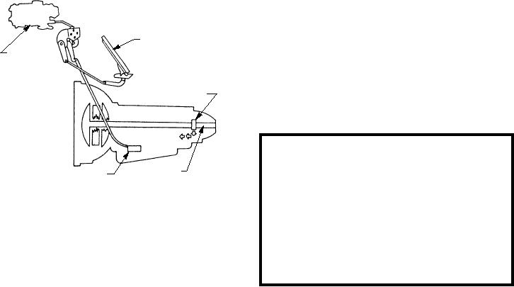
ACCELERATOR PEDAL
use a pump at both the front and rear of the
CARBURETOR
transmission. This allows the vehicle to be "push
s t a r t e d ," w h e r e a s w i t h t h e s i n g l e p u m p ,
"push-starting" cannot be accomplished, since the
GOVERNOR
engine must be operating to drive the torque converter
and the pump.
HYDRAULIC
CONTROL
WARNING
UNIT
OUTPUT
Pushing or pulling a vehicle equipped with an
SHAFT
THROTTLE VALVE
automatic transmission is extremely dangerous
ASf02066
and can result in damage to the equipment and
Figure 2-66.--Typical throttle valve and linkage.
injury or death to personnel. A vehicle equipped
with an automatic transmission should not be
Figure 2-66 shows a typical throttle valve and
pushed or pulled except in an extreme emergency,
linkage. The throttle valve delays the upshifting and
and then only after all possible precautions are
regulates oil pressure proportional to the accelerator
taken to eliminate the dangers involved.
pedal position or carburetor throttle opening. The
governor valve causes the upshifting and regulates oil
pressure proportional to the transmission output shaft
Pressure Regulator
speed.
The kickdown valve provides a means of forcing a
Oil from the pumps must be delivered to the
downshift to a lower gear ratio when it is desirable,
operating units under regulated pressure. To obtain this
such as when accelerating rapidly. The torque
regulated pressure, a pressure-regulating valve is
converter control valve controls the pressure and flow
incorporated into the system pressure line. Figure 2-67
of oil to the torque converter and to the lubricating
shows an oil pressure regulator. Oil from the pump or
passages of the transmission. Valves, metering
pumps flows to the chamber between two lands of a
orifices, or restrictions are added to the hydraulic
spool valve. Movement of the valve in one direction is
system to help time and smooth out the operations of
limited by a mechanical stop. Movement in the other
the transmission.
direction is limited by a spring calibrated to the
required system pressure (usually around 80 to 90 psi).
HYDRAULIC CONTROL SYSTEM
As shown in figure 2-67, oil flows from the
chamber of the regulator valve to the manual valve and
The h y d r a u l i c c o n t r o l s y s t e m m a k e s t h e
back to the rear of one large land in the regulator valve.
transmission fully automatic, and to do its job
This area of the regulator valve is known as the
completely, must consist of a fluid source, pressure
secondary reaction area. Also notice there is an oil flow
supply system, hydraulic operating units, and control
from the pumps to the rear of the small land of the
units for regulating both fluid flow and pressure.
secondary reaction area. This area is known as the
The fluid source is the fluid contained in the
primary reaction area. In looking at the two reaction
transmission oil pan, normally referred to as a sump.
areas, notice the working areas of the lands. There will
The fluid is strained through a filter as it flows from the
be no regulated pressure (at least not 80 to 90 psi) until
sump to the pump or pumps.
oil has reached the secondary reaction area of the
valve.
The hydraulic system must maintain the oil under
pressure for its various components to function
After the oil has entered the secondary reaction
properly. It is the job of the pump or pumps to remove
area, the force of the oil acts on both the large and small
oil from the sump and deliver it under pressure to the
lands in the area. When the pumps have supplied
systems. The pumps can be of several different
sufficient pressure, the resulting force acting on the
designs, however, most manufacturers use the internal
large land of the secondary reaction area moves the
valve to the left against the spring. This movement
gear, constant displacement pump.
2-51

