
WHEEL RIMS
This rim is used on rear axles of towing tractors and
similar heavy duty vehicles. Rims are mounted with
The three types of rims most commonly used on
the demountable flange outboard on single wheel
SE are the solid rims, split rims, and demountable
installations, and facing each other on dual wheel
flange rims.
installations.
Solid Rims
TIRES
Solid rims are made in one piece and are
The types of tires most commonly used on SE are
permanently fastened to the wheel hub (fig. 2-94).
bias ply, bias belted, radial, tubeless, and solid rubber
They feature a well in the center that permits mounting
tires.
and demounting of the tire. This type of rim is often
Bias Ply
referred to as a drop center rim, and is generally used
on smaller vehicles and light trucks.
In bias ply tires, tire cords are arranged in two or
more (even number) plies, depending on the strength
Split Rims
desired in the finished tire. The cords, or plies, cross
Split rims consist of two, usually identical, halves
the tire circumference at an angle, usually 30 to 40
secured together by tie bolts. They are usually mounted
degrees. This design provides rigidity in both sidewall
on handling equipment, small trailers, and front wheel
and tread. A disadvantage is that bias ply tires squirm
assemblies of towing tractors. When assembling split
more and tend to run hotter than belted bias or radial
rim wheels, you must ensure that steel and aluminum
tires.
halves are not mixed. Mixing different types of wheel
Bias Belted
halves may cause cracks and wheel failure.
Constructed similarly to bias ply tires, belted tires
Demountable Flange Rims
will have an additional two or more layers of fabric
The demountable flange rim consists of two parts:
(belts) under the tread. The cords in the belt also run at
the rim base and the demountable flange. The
an angle, about 25 degrees to the circumference. This
demountable flange (split ring) holds the tire by
construction provides the sidewall stiffness of the bias
ply with increased strength and stiffness in the tread.
interlocking with the rim base when the tire is inflated.
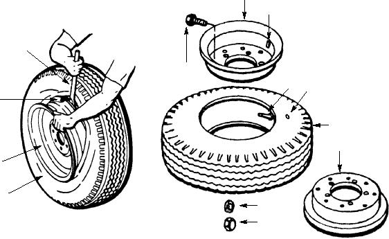
1.
LOCKWASHER
3
2.
NUT
4
3.
OUTER RIM HALF
1. TIRE
4.
VALVE STEM HOLE
2. RIM
5.
VALVE STEM
3. FLANGE
6.
TIRE BALANCE MARK
1
7.
TIRE
8.
INNER RIM HALF
9
9.
TIE-BOLT
5
6
3
7
8
2
1
1
2
A. SOLID RIM
B. SPLIT RIM
ASf02094
Figure 2-94.--Solid and split rims.
2-79