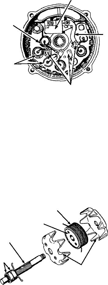
BRUSH
HOLDER
ASSEMBLY
CAPACITOR
HEAT
SINK
LEAD
ATTACHING
ASf06024
NUTS
Figure 6-24.--View of an ac generator slip ring end frame assembly.
pulley or the rotor shaft. Remove the pulley, fan, and
Remove the bolts and separate the drive end frame
collar. Then separate the drive end frame from the rotor
and rotor assembly from the stator assembly by
assembly. Remove the three stator lead attaching nuts
inserting a flat tool in the stator frame slot. The
from the diodes, and remove the stator assembly from
separation is made between the stator frame and the
the slip ring end frame assembly.
drive end frame because the stator windings are
connected to the diodes in the slip ring end frame
No further disassembly is required to make
assembly. Once the drive end frame and the rotor
electrical tests on the four major subassemblies and
assembly are removed, tape the slip ring end frame
their components.
assembly rotor shaft bearing to prevent entry of dirt,
and also tape the bearing area of the rotor shaft on the
Testing the Rotor
slip ring end. Place the rotor assembly in a soft-jawed
vise and tighten just enough to allow removal of the
The rotor is tested for grounds, shorts, and opens.
drive pulley retaining nut. Be careful not to damage the
To test for grounds, connect a test lamp or an ohmmeter
FIELD
COIL
IRON
SPOOL
ROTOR
SHAFT
SLIP
RINGS
ROTOR
SEGMENTS
ASf06025
Figure 6-25.--Exploded view of an alternator rotor.
6-21

