
ROTOR
STATOR
RECTIFIER
F2
F1
BAT.
BATTERY
+
IGNITION
SWITCH
BAT.
F1
F2
P
P
N
VOLTAGE REGULATOR
SW
TRANSISTOR
FIELD RELAY
ASf06037
SEMITRANSISTORIZED REGULATOR
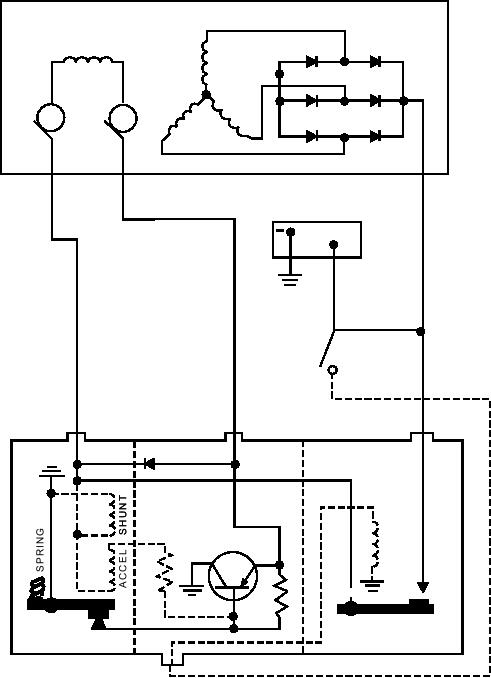
Figure 6-37.--Ac charging circuit using a semitransistorized regulator.
Note in figure 6-37 that the voltage regulator
results in less current through the voltage regulator
accelerator winding (connected to the regulator F2
shunt winding, and consequently less magnetism. The
terminal and to ground through a resistor and the
weakened magnetic pull on the armature is then
voltage regulator contacts) carries no current at all
overcome by the spring, which pulls the armature away
when the voltage regulator contacts are open. Thus,
from the core and closes the contacts.
when the contacts open, the magnetic pull, created by
This cycle repeats many times per second, resulting
the shunt winding connected directly to ground, allows
in a constant generated voltage, which is determined by
the armature spring to close the contacts in a very short
the adjusted spring tension. With higher spring tension,
time interval. Once closed, the magnetic pull of the
more magnetic pull will be required to open the
accelerator is restored and is added to the magnetic pull
contacts. Therefore, the voltage will rise to a higher
of the shunt winding. The contacts immediately reopen.
value before the contacts will open, and a higher
Therefore, the accelerator winding speeds up or
voltage setting results. Similarly, reduced spring
accelerates the frequency of vibration.
tension gives a lower voltage setting.
6-31