
When the ignition switch is opened, the field relay
shunt winding is disconnected from the battery. A
spring then pulls the armature away from the core,
opening the contacts and disconnecting the rotor
windings from the battery.
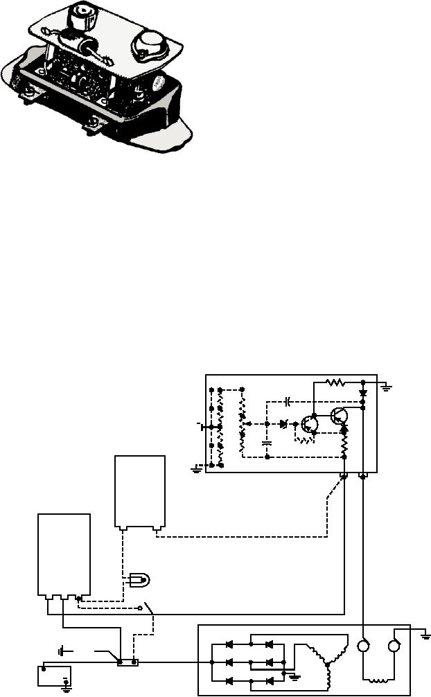
FULLY TRANSISTORIZED REGULATOR
The transistor regulator shown in figures 6-38 and
6-39 is a model used on some Navy equipment. It has
only two terminals, contains no moving parts, and
limits the alternator voltage through the combined
ASf06038
Figure 6-38.--Fully transistorized regulator.
action of the two transistors.
The resistor connected across the emitter and base
From the schematic diagram shown in figure 6-39,
of the transistor acts to prevent emitter-to-collector
you can see that the charging circuit consists of the
current leakage when the voltage regulator contacts are
alternator, the regulator, the battery, the field relay, the
open during high temperatures, even though the
junction block, the wiring, and either an ammeter or an
contacts are open.
indicator light.
The diode (upper center) is connected directly
When the ignition switch is closed, the winding in
across the rotor windings. When the voltage regulator
the field relay is connected to the battery. The resulting
contacts open, the sudden interruption of field current
magnetism created in the core overcomes the relay
causes a voltage to be self-induced in the field coils of
spring tension and pulls the armature toward the core,
the rotor. The diode provides an alternate circuit in
closing the contacts. This completes the circuit from the
which the self-induced current can flow within the
battery to the POS terminal of the regulator. It also
windings of the rotor. Without the diode, this voltage
connects the winding of the indicator light relay to the
surge would damage the transistor.
battery.
FULL TRANSISTOR REGULATOR
R2
06
D3
R7
TR1
03
C1
TR2
R8
0
R5
D2
+
R9
C2
R4
03
R1
R3
INDICATOR LIGHT RELAY
R10
06
FIELD
RELAY
INDICATOR
LIGHT
IGNITION
SWITCH
F1
F2
STATOR
RECTIFIER
LOAD
JUNCTION
BAT.
BLOCK
+
BATTERY
ROTOR
ASf06039
ALTERNATOR
Figure 6-39.--Ac circuit using a fully transistorized regulator.
6-32