
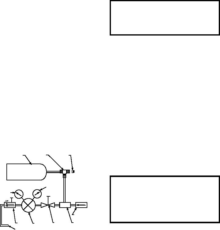
the cylinder pressure decreases. The regulator also
operator adjusts the pressure regulator to the desired
contains an adjustable relief-venting valve to prevent
pressure, the pressure registers on the delivery pressure
over pressurizing the system being charged.
gauge. The regulated nitrogen pressure is then fed
through the bleed valve, which is kept in the FLOW
C Y L I N D E R P R E S S U R E G AU G E . -- T h e
cylinder pressure gauge indicates the pressure
position during charging, to the servicing hose.
remaining in the cylinder.
CHARGING AN EXTERNAL SYSTEM.--
D E L I V E RY P R E S S U R E G AU G E . -- T h e
Follow these steps to charge an external system from a
delivery pressure gauge indicates the regulated
walk-around bottle. (Refer to figures 9-2 and 9-3 for
delivery pressure to which the regulator is set during a
controls and indicators.)
charging operation.
BLEED VALVE.--The bleed valve controls the
WARNING
flow of nitrogen from the regulator to the servicing
Always open valves slowly. Servicing hose should
hose, and it allows the user to bleed the servicing hose
be slack when under pressure and should not be
before removing it from the system being charged. It is
stretched to make a connection.
spring-loaded and is designed to automatically shut off
the nitrogen flow before it vents the servicing hose.
N I T RO G E N H O S E . -- T h e 9 6 - i n c h , h i g h -
1. Ensure the bleed valve, the pressure regulator,
pressure, nitrogen hose provides a connection between
and the shutoff valves are closed.
the unit and the item to be charged.
NOTE: Remember that pressure regulators turn
RECHARGE VALVE.--The recharge valve is
opposite to other valves. That is, pressure regulators
open only during recharging to allow nitrogen to flow
open with a clockwise rotation and close with a
into the cylinder. The valve is closed during all other
c o u n t e r c l o c k w i s e r o t a t i o n . Ta ke c a r e w i t h t h e
operations to prevent nitrogen from the cylinder
regulator because the threads inside are brass and will
escaping to the atmosphere.
strip very easily.
Operation
2. Open the shutoff valve and read the cylinder
pressure on the cylinder pressure gauge. It
Figure 9-3 is a schematic flow diagram of the
should be higher than the system to be charged.
portable high-pressure cylinder. The high-pressure
(Maximum pressure is 3,000 psi.)
nitrogen in the cylinder is fed through the shutoff valve
and entrapped at the inlet of the pressure regulator.
3. Adjust the pressure regulator to the desired
delivery pressure. Read the pressure on the
The cylinder pressure gauge indicates the amount
delivery pressure gauge.
of pressure at the pressure regulator inlet. Once the
4. Open and close the bleed valve quickly to allow
NITROGEN
CYLINDER SAFETY NUT
a short burst of nitrogen to clean and purge the
CYLINDER
AND DISCS
TEE
hose. Then, attach the hose to the system to be
charged.
WARNING
CYLINDER
DELIVERY
When using the walk-around bottle to inflate tires,
PRESSURE
PRESSURE
GAUGE
GAUGE
always use an approved remote inflator assembly
to prevent possible personal injury. NAVAIR
17-1-123 covers the requirements for the remote
inflator assembly.
RECHARGE
VALVE
SHUTOFF
BLEED
MANIFOLD
PRESSURE
VALVE
VALVE
REGULATOR
SERVICING
5. Slowly rotate the bleed valve to the FLOW
HOSE
ASf09003
position, allowing nitrogen to flow into the
Figure 9-3.--Portable high-pressure nitrogen cylinder
servicing hose.
schematic.
9-4