
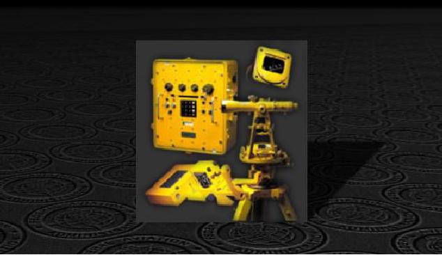
Figure 4-3 -- Compass calibration set.
The pad surface is marked every 15 degrees to indicate magnetic bearings beginning
with magnetic north (see Figure 4-4). The taxiway to the compass rose is generally
placed perpendicular to the taxiway with the least traffic. Brass or bronze is used in the
construction of a compass rose since neither metal affects magnetic instruments. Other
metal objects should be kept clear of the pad when the compass rose is in use. In the
calibration of an aircraft compass, all electrical equipment is turned on and the engines
are kept running to simulate actual flight conditions.
4-5