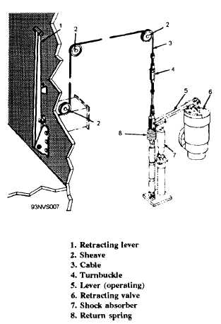
Figure 3-7.—Retracting lever installation.
NOTE
The ideal condition is that tension be
kept on the purchase cable from the
beginning of the retracting stroke until the
ram is in its battery position. An
interruption of the stroke generally disrupts
this condition and creates cable backlash,
which results in cable slack on the engine.
If an emergency arises involving the safety of
personnel or equipment, and an interruption of
full-speed retraction is necessary, the following
procedures are recommended to prevent possible
damage, such as a tight kink, to the purchase cable:
1. Resume retracting very slowly at first to rid
the cable system of slack.
2. Resume full-speed retraction only after the
cable slack has been eliminated and the cable has
tension.
3. Inspect sheave damper sheaves for proper
seating of the purchase cable on completion of
retraction.
A shock absorber like the one found on
automobiles is installed on the operating lever to
eliminate chattering of the retracting valve during
closing.
ACCUMULATOR SYSTEM
The Mk 7 arresting engine has a
recirculating-type hydraulic system. During
arrestment, the hydraulic fluid is forced from the
main engine cylinder, through the CRO valve, to the
accumulator. An initial air charge of 400 psi in the
accumulator builds up to approximately 650 psi
during arrestment. This increased pressure is used
to force the fluid from the accumulator into the
fluid cooler, thus forcing fluid from the previous
arrestment, already cooled by the cooler, out of the
cooler, through the retracting valve, and into the
main engine cylinder, returning the engine to its
BATTERY position.
The accumulator (fig. 3-8) is a long, steel
cylinder mounted horizontally in saddles on the
engine structure, with the fluid end toward the fixed
sheaves. Inside the accumulator is a floating piston
that separates the air side of the accumulator from
the fluid side. The air end of the accumulator is
flanged and bolted to the air expansion flask
manifold. The fluid end of the accumulator is
flanged and bolted to the accumulator nozzle, which
contains a fluid-level indicator, a device used to
indicate to the engine-room operator whether the
system has the proper amount of fluid. The fluid
indicator registers the following three
conditions—FILL (insufficient amount of fluid in the
system), DRAIN (excessive amount of fluid in the
system), and BATTERY (proper amount of fluid in
the system).
The floating air-fluid separator piston is made of
aluminum alloy and has two sets of V-ring packing
(one for the air side and one for the fluid side),
which prevent air from leaking past the piston into
the fluid side of the accumulator, or fluid from
leaking into the air side. Two slipper cages with
phenolic slippers are fitted onto the piston to act as
a bearing surface between the piston and the
cylinder wall. The phenolic slippers are replaceable
and must be replaced when the maximum allowable
wear has been reached.
This is to prevent
3 - 12