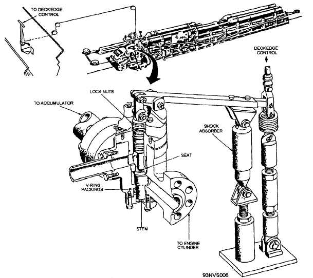
Figure 3-6.—Ceneral location
threaded portion is for an adjusting nut and a
locknut used to adjust the stroke of the plunger and
valve stem. The stroke is adjusted to 0.678 (11/16)
of an inch. The clevis connects the operating lever
and the plunger. The opposite end of the operating
lever is connected to a tie rod, a return spring, and
a control cable by another clevis. The control cable
is attached to the T-shaped retracting handle at the
deckedge control station. See figure 3-7.
Retracting Lever
There is a retracting lever for each arresting
engine located at the deckedge control station (fig.
3-7.) The retracting lever provides a remote means
of opening the retracting valve from a location
where the operator will have full visibility of
recovery operations.
of the retracting valve.
When the operator pulls down on the retracting
lever, the force transmitted through the control
cable lifts the end of the operating lever that is
attached to the return spring and tie rod. The
operating lever has a pivot point on the block
mounting of the valve.
As the one end of the
operating lever is lifted, the end connected to the
plunger pushes down on the plunger and valve stem,
allowing fluid flow through the valve from the
accumulator or fluid cooler to the engine cylinder,
thus forcing the ram and crosshead back to their
battery position. After retraction is complete, the
retraction lever is released and the return spring
pulls down on the operating lever, which in turn
pulls upon the plunger and valve stem, which closes
the valve. See figure 3-7.
3-11