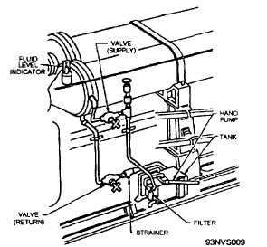
arresting engines, a fluid replenishment system is
provided. See figure 3-9.
The fluid replenishment system consists of a
small hand pump, mounted on the lower engine
frame, that is connected by piping to the engine
accumulator and a 6-gallon stowage tank. If,
because of leakage or fluid contraction while the
engine crosshead is in BATTERY, the fluid-level
indicator reads FILL, the supply valve in the piping
is opened and the hand pump is operated until the
indicator reads BATTERY. A fluid filter is located
in the supply line to filter the fluid being pumped
into the accumulator. If the fluid-level indicator
reads DRAIN, the return valve located in the return
line is opened, and fluid from the accumulator
drains into the replenishment tank. When the
fluid-level indicator reads BATTERY, the return
valve is closed.
FLUID STOWAGE SYSTEM
A fluid stowage system (fig. 3-10) is provided to
stow fluid from the arresting engine during
maintenance and to transfer fluid back to the engine
after maintenance is complete.
Because of the
difference in the fluid capacity of the Mods 2 and 3
engines, the capacity of the fluid stowage systems
differs. The fluid stowage system consists of one
common, steel stowage tank that serves all the
arresting engines installed on a particular ship. It is
equipped with piping valves from the accumulator to
the stowage tank.
The capacity of the fluid stowage tanks is
Mod 2, 600 gallons, and Mod 3, 700 gallons. The
stowage tank is capable of storing all the fluid in the
system of one arresting engine. Ship’s low-pressure
air is used to force the fluid to and from the
stowage tank. A pressure relief valve, which is set
at 120 psi, is provided to prevent excessive pressure
buildup. The relief valve is located on the stowage
tank.
Fluid Cooler
During continuous arresting operations, the
engine fluid temperature rises because of friction of
the fluid moving through the engine, control valve,
and piping. To maintain extended pendant engine
operation, the fluid temperature is reduced by the
fluid cooler.
(See fig. 3-11.) The maximum
operating temperature for all arresting engines is
170°F. Prolonged operation at this temperature
limit is not recommended.
The fluid cooler is mounted in saddles on top of
the engine structure adjacent to the accumulator.
Fluid coolers are used on all Mk 7 arresting
engines serving a pendant engine. Engine fluid, as
it is returned from the accumulator to the main
engine cylinder during retraction of the engine,
flows through the fluid cooler body. Heat from the
engine fluid is transferred to cool service water (salt
water) flowing at 100 gallons per minute through
tubes within the cooler body.
The fluid cooler body is a cylindrical steel shell
with two flanged ends. The body of the cooler has
four equally spaced holes in each end to provide a
means of draining and venting the cooler. These
holes are normally closed with pipe plugs or vent
valves. One end of the cooler has a cooler head
assembly that forms a cap for one end of the body
and provides an inlet for engine fluid coming from
the accumulator. The cooler head assembly is a
disc-shaped steel casting with an opening in the
center, which is flanged to the fluid inlet piping. A
copper annealed gasket is used as a seal between
the cooler head and the body to prevent fluid
leakage. The head is bolted to the body. The
coolant (salt water) flows through a tube assembly
that consists of 107 U-shaped copper tubes
supported inside the cooler body by three circular
baffle plates. A tube head is bolted to the end of
the cooler, opposite of the cooler head. A copper
annealed gasket is used as a seal against fluid
leakage between the tube head and the cooler body.
3-14
Figure 3-9.—Fluid replenishment system.


