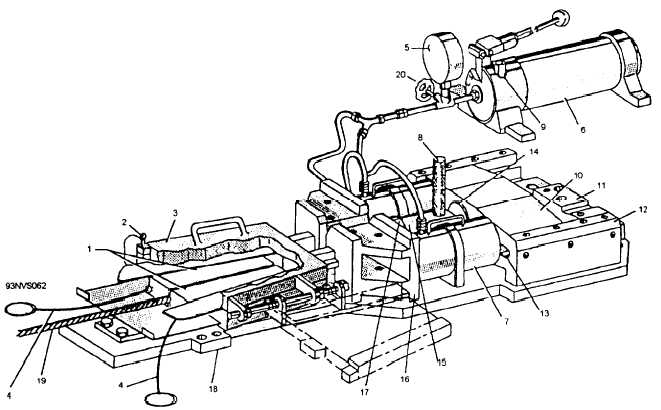
1. Wedge set
2. Safety lock pin
3. Lid
4. Retracting cables
5. Tension gauge
6. Hydraulic pump
7. Ram
8. Pin
9. Selector valve
10. Crosshead
11. Crosshead stop
12. Rail support
13. Rail
14. Crosshead terminal
15. Clevis socket
16. Strongback
17. Cable terminal
18. Base plate
19. Cable
20. Choker valve
21. External load release valve
Figure 3-62.—Wedge-type proof-loading machine (dual ram).
7. Screw the clevis socket on the cable
terminal.
8. Place the cable between the wedges and
connect the clevis socket to the crosshead terminal
with the pin.
9. Manually move the crosshead into the rams,
making certain that the adapter attached to each
end of the ram engages its respective guide hole in
the face of the crosshead.
10. Release the wedges, close the lid, and insert
the safety lock pin.
11. Using chalk, masking tape, or some other
means, mark the cable a measured distance from
the wedge set. This procedure provides a means for
checking cable slippage while the system is being
pressurized.
12. Visually inspect
the socket tester to
make certain that all components are securely
attached.
CAUTION
Do not open the choker valve during
operation of the hand pump, as this will
‘result in excessive pressurization of the
3-62


