sure-relief valve (set at 4 psi), a pressure gage, and a
portable inertness analyzer connection.
A fixed eductor is installed in the cofferdam to
remove any seawater or gasoline that might escape
from the storage tanks. The eductor is fitted with two
suctions: one near the centerline at the forward end
of the cofferdam and the other near the centerline at
the after end of the cofferdam.
The controls for the eductor are located in a
watertight box on the pump room deck.
Two static-head liquid-level gages, or electronic
sensors, are installed in each cofferdam to indicate
the presence of leakage into the compartment. One is
located on the centerline in the forward end of the
cofferdam and the other on the centerline in the after
end. This arrangement makes it possible to determine
the presence of leakage, regardless of the trim of the
ship.
Access to the cofferdam is gained through a
bolted manhole cover in the pump room deck.
Normally, the cofferdam manhole cover is located
directly over the outer tank manhole cover.
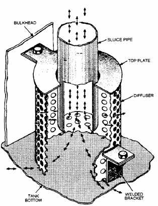
Storage Tank Diffuser
The diffuser (fig. 6-6) reduces turbulence when
gasoline or seawater enters the storage tanks.
Diffusers are mounted on the bottom of the gasoline
storage tanks around the end of each sluice pipe and
seawater supply riser. They are bolted to clips or
brackets that are welded to the bottom of the tank
and to the bulkhead.
The diffuser is a perforated cylinder with an
open bottom, and it has a top plate with an opening
for the gasoline or seawater supply pipe. The opening
in the top plate is larger than the outside diameter of
the supply pipe, which permits the pipe to move with
the movement of the ship’s structure. The total area
of the perforations in the diffuser is five times that of
the area of the supply pipe. Gasoline or water enters
the diffuser in a single stream and is broken into
smaller streams as it passes through the holes in the
cylinder. The distribution of flow over a large area
reduces turbulence.
Gaging Equipment
Two different types of gages are currently used
in the gasoline tanks to determine the amount of
gasoline within the tanks. These gages are the water-
filled, static-head type, and the TLI.
Figure 6-6.—MOGAS storage tank diffuser.
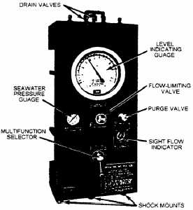
The water-filled, static-head gasoline gage (figs.
6-7 and 6-8) provides an accurate means of
determining the amount of gasoline in the saddle-type
storage tanks. It accomplishes this task by sensing the
differential created, as the plane of cleavage between
Figure 6-7.—Level indicating panel (front view).
6-8