indicates its findings on a dial that is calibrated in
gallons. This gage consists of three basic units: the
bellows, torque tube, and dial mechanism.
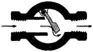
The flow indicator (fig. 6-10) provides visual iden-
tification of the flow of seawater through a pipeline. The
indicator has a hinged flapper suspended from the body
so it rests against the inlet passage at no flow. As liquid
begins to flow, the flapper swings outward to a position
generally proportional to the flow rate.
The in-tank reservoir connecting lines are gasoline-
tight, cylindrical tanks with a nontight flanged cover.
They are open to liquid pressure near the top by two
holes directly opposite each other. The in-tank reser-
voirs are brazed to the ends of connecting lines. One is
located near the top of the tank and the other located
near the bottom of the same tank. Connecting lines
terminate 1/2 inch off the bottom of the reservoir. The
in-tank reservoirs are filled with seawater because of
purging. The connecting lines are purged with seawater
to prevent gasoline from entering the pump room
through the lines.
The flow-limiter valve is a globe-type needle valve
used to reduce seawater pressure to the desired pressure.
It is located between the firemain supply and the purge
valve.
The seawater pressure gage indicates the pressure
of the seawater supply and is located between the flow-
limiter valve and the purge valve.
With one exception, the TLI used in MOGAS tanks
is just like the TLI used in JP-5 tanks. The float for the
TLI used in MOGAS systems is constructed of Hycel.
This material is designed to float on water and sink in
fuel. That means the float will be at the cleavage line
(interface) of the water and MOGAS. Refer to chapter
4 for information on TLI components and operations.
SEAWATER PIPING AND VALVE
ARRANGEMENT
The seawater system supplies seawater (under pres-
sure) to the outer tank to force gasoline up to the transfer
(gasoline booster) pump. It also provides a means for
flushing and draining the storage tank, and limits the
Figure 6-10.—Flow indicator.
amount of pressure that can be applied to the tanks at
maximum pump capacity.
Seawater is supplied directly from the sea, through
a sea chest located in the cofferdam around the storage
tanks. A steel grating installed in the opening of the
ship’s bottom prevents large objects from being drawn
into the system. Steam is used for cleaning out the sea
chest in the event of clogging. Steam has a two-fold
effect for cleaning purposes. It can be supplied at an
adequate pressure for blowing out any debris, and it also
provides a “cooking effect” to remove remaining gaso-
line vapors as well. A shutoff valve is located between
the sea chest and the sea chest supply riser. This valve
is LOCKED OPEN.
The sea chest supply riser connects directly to the
suction header of the seawater pump. An additional
shutoff valve is installed in this line at the pump room
level.
The motor-driven, centrifugal seawater pump is
located in the MOGAS pump room, and the motor is in
the adjacent pump motor room. The shaft connecting
the pump to its motor passes through a watertight stuff-
ing box in the bulkhead. The pump takes suction from
the suction header and discharges into a discharge
header. The pump suction line is fitted with a basket
strainer, a one-way check valve, and a compound gage.
The discharge line contains a pressure gage and a shut-
off valve. On centrifugal pumps, the pump inlet is
always larger than the discharge line.
NOTE
LPDs have a separate seawater pump room,
located in the starboard shaft alley.
The discharge header is connected to the outer tank
seawater supply riser and the seawater expansion tank
fill line. Shut off valves installed in this line can be used
to direct pump discharge pressure into the outer tank for
pressurizing the system during normal operations or
filling the expansion tank.
The expansion tank is a 500-gallon tank kept full of
seawater. Its purpose is to keep the MOGAS tanks full
at all times by compensating for contraction of the
MOGAS.
The outer tank seawater supply riser terminates in
a diffuser at the bottom of the outer tank. This line
contains a spectacle flange (or pipe blind) and a steam-
out connection. The spectacle flange is rotated to the
closed position when steam is injected either here or at
the outer tank manhole cover for steaming tanks.
The overboard discharge line is led upward in a loop
from the expansion tank and then overboard just above
6-10