
OIL SYSTEM COMPONENTS
As we just discussed, there are two primary
types of oil systems. Some of these parts are
unique to one type of system, while other parts
are used in both systems. The following para-
graphs cover oil system parts regardless of type
unless otherwise noted. The main parts of a
typical oil system include an oil tank, oil pumps,
valves, filters, and chip detectors. Other parts are
oil coolers, oil jets, gauge connectors, vents, and
oil system seals.
Oil Tanks
The oil tank stores the system oil supply. An
oil tank may be a simple sealed container (similar
to a car's fuel tank) where oil is gravity fed to the
engine. Older low-performance aircraft engines
could use this simple tank design. Today's high-
performance aircraft require a more complicated
pressurized type of oil tank; this assures positive
lubrication during all flight conditions.
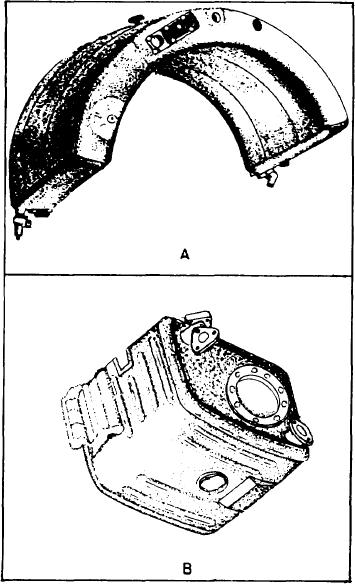
The dry-sump oil system uses an oil tank
located either in the airframe or mounted on the
engine. See figure 5-4. Oil tanks mounted on the
airframe are normally located within or near the
engine compartment. Additionally, designers
place it high to gain as much advantage as possible
from gravity flow to the oil pump inlet.
A view of a representative oil tank is shown
in figure 5-5. It shows a welded aluminum tank
with an oil capacity of 3.25 gallons and a
0.50-gallon foaming space. The tank is designed
to furnish a constant supply of oil to the engine
in any attitude, and during negative g loading or
Figure 5-4.-Dry-sump oil tanks; (A) engine mounted;
(B) engine or airframe mounted.
forces. This is done by a swivel outlet assembly
mounted inside the tank, a horizontal baffle
mounted in the center of the tank, two flapper
at a tangent. The air released is carried out
check valves mounted on the baffle, and a positive
vent system.
through the vent system in the top of the tank.
The swivel outlet fitting is controlled by a
The vent system inside the tank is so arranged that
weighted end, which is free to swing below the
the airspace is always vented. This includes times
when the aircraft is decelerating and oil is forced
baffle. The flapper valves in the baffle are
normally open. They close only when the oil in
to the top of the tank. However, most oil tanks
have a pressurized oil tank to assure a positive
the bottom of the tank tends to rush to the top
flow of oil to the oil pump inlet. The tank is
of the tank. This happens during decelerations
pressurized by running the vent line through an
and inverted flight. Oil trapped in the bottom of
adjustable check relief valve.
the tank is picked up by the swivel fitting without
Other features common in oil tanks area sump
any interruption in the flow of oil.
with drain and shutoff valves in the bottom of
All oil tanks provide an expansion space. This
the tank. The drain valve permits oil to be drained
allows for oil expansion from heat and oil foam-
for oil changes. An oil shutoff valve is a motor-
ing. Some tanks also have a deaerator tray
operated, gate-type valve attached to the oil sump.
for separating air from the oil. Usually these
This valve can be operated electrically or manually
deaerators are of the can type, with oil entering
5-8