
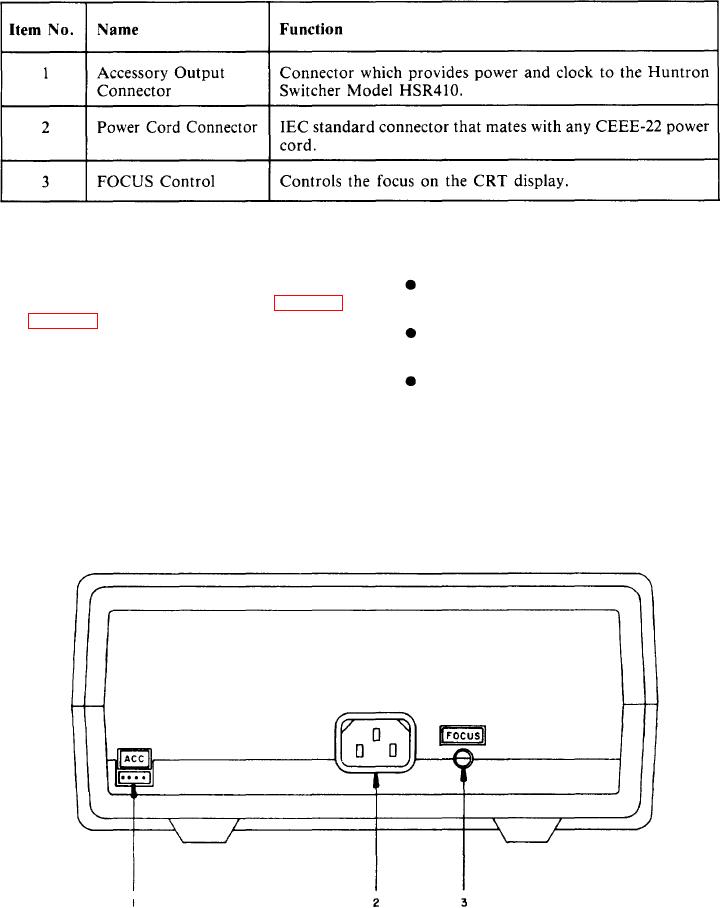
Table 2-5.-Back Panel Controls and Connectors
207X
Quadrant 2 displays negative voltage (-V)
Back Panel. --Secondary controls and con-
nectors are located on the back panel (fig. 2-30
and positive current (+I)
and table 2-5).
Quadrant 3 displays negative voltage (-V)
CRT Display. --The signature of the part
and negative current (I)
under test is displayed on the CRT. The display
Quadrant 4 displays positive voltage (+V)
has a graticule consisting of a horizontal axis that
and negative current (I)
represents voltage, and a vertical axis that
represents current. The axes divide the display into
The horizontal axis divides in eight divisions,
four quadrants. Each quadrant displays different
which allows the operator to estimate the voltage
portions of the signatures.
at which changes in the signature occur. This is
Quadrant 1 displays positive voltage (+V)
useful in determining semiconductor junction
voltages under either forward or reverse bias.
and positive current (+I)
207X
Figure 2-30.-Back panel.
2-51