
Figure 6-73.-Flap position indicating system.
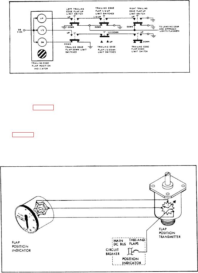
indicator rotor shows the amount of travel of the
indicators show UP, 1/2, DN (down), and barber
flaps in percent of full extension. The transmitter
pole. The indicator (fig. 6-73) energizes through
mounts on the flap drive control unit and actuates
limit switches.
by the control actuating mechanism.
Other aircraft show the position of the flaps
using the dc synchro system of remote indication.
Integrated Position Indicator
This system consists of a transmitter and an
indicator (fig. 6-74). A change in flap position
In many jet aircraft, the design of position
moves the transmitter rotor, and a similar
indicators combines various systems into one
rotor movement occurs in the indicator on the
instrument. This instrument is the integrated
instrument panel. A pointer attached to the
Figure 6-74.-Dc synchro flap position indicating system.