transmitter synchro. The pressure transmitter
POSITION INDICATING SYSTEM
(DC SYNCHRO SYSTEM)
synchro sends an electrical signal to the receiving
synchro within the indicator. The receiving
A dc synchro system is a method of showing
synchro's rotor links mechanically to the indicator
a remote mechanical condition. Specifically, these
pointer. The pressure indicator contains two
synchros that attach mechanically to two separate
systems show movement and position of wing
flaps, cowl flaps, oil cooler doors, or similar
pointers. When the HYD PRESS SELECTOR
movable parts of the aircraft.
switch is in the No. 1 and No. 2 FLT CONT
position, the pointers indicate the pressure of each
system. When the HYD PRESS SELECTOR
The system consists of a transmitter, an
switch is in the UTILITY position, the synchros
indicator, and connecting wires. A dc voltage
from the aircraft's electrical power system supplies
connect in electrical parallel. This causes the
the voltage to operate the system. The transmitter
pointers to act as one. This type of arrangement
mechanically connects to the movable device that
saves instrument panel space.
is actually supplying the positioning data. The
PNEUMATIC PRESSURE SYSTEMS
indicator repeats this information on a properly
calibrated scale in the indicator on the instrument
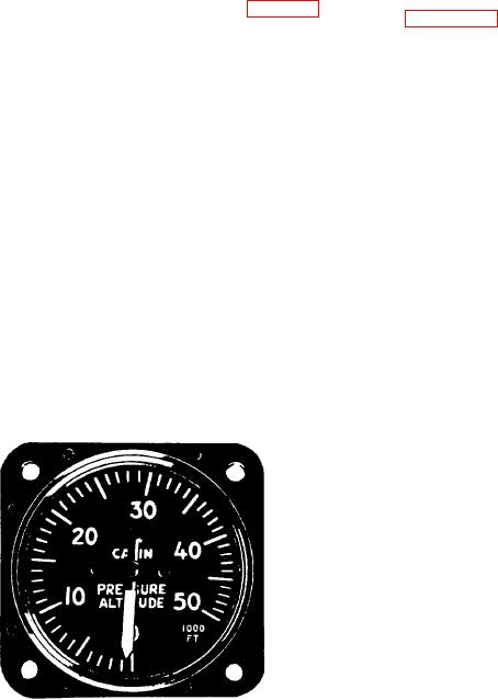
The cabin pressure altitude indicator (fig. 6-70)
panel. Figure 6-71 illustrates a complete three-wire
is a sensitive altimeter that measures cabin
system.
pressure. The instrument contains a sensitive
diaphragm that expands or contracts with changes
in cabin pressure. The altitude equivalent of cabin
Transmitter
pressure shows on the dial, in increments of 1,000
feet. The range is from 0 to 50,000 feet. An
The three-wire system transmitter consists of
opening in the back of instrument case allows it
a continuous circular toroidal resistance winding
to sense cabin pressure. You can also use this
with two diametrically opposite brushes con-
instrument to reflect pressure suit altitude rather
tinuously touching the winding. These brushes
than cabin altitude when wearing a pressure suit.
apply dc to the winding. The brushes rotate with
the movement of the aircraft part to which they
are mechanically attached.
CAUTION
Remove the cabin pressure altitude
indicator if the aircraft is to undergo a
Indicator
cabin pressurization test on the ground.
The three-wire system indicating element
Failure to remove the indicator will result
consists of an annular core, a permanent magnet
in damage to the instrument from excessive
rotor, a damping cylinder, and three field coils.
pressure.
The leads between the coils connect to the three
taps of the transmitter winding. As voltages at the
transmitter taps vary through brush rotation, the
distribution of current in the indicator coils varies.
This causes the resulting magnetic field of the
three coils to position the pointer's permanent-
magnet rotor.
A copper cylinder provides a damping effect.
The induced eddy currents in this cylinder oppose
movement of the rotor. This reduces the tendency
of the pointer to oscillate.
Landing Gear
An example of a position indicating system is
Figure 6-70.-Cabin pressure altitude indicator.
a wheel position indicator. The system consists

