
voltmeter is now out of phase with the voltage
applied to the transformer.
In an actual capacitive-type fuel gauge, the
input to a two-stage amplifier takes the place of
the voltmeter. It amplifies the signal resulting
from an imbalance in the bridge circuit. The
output of the amplifier energizes a winding of the
two-phase indicator motor. The other motor
winding is the line phase winding. It receives
constant power from the same voltage that powers
the transformer in the bridge circuit. However,
a series capacitor shifts its phase by 90 degrees.
As a result, the indicator motor is phase sensitive.
This means that the indicator motor will operate
in either direction, depending on whether the tank
unit capacitance is increasing or decreasing.
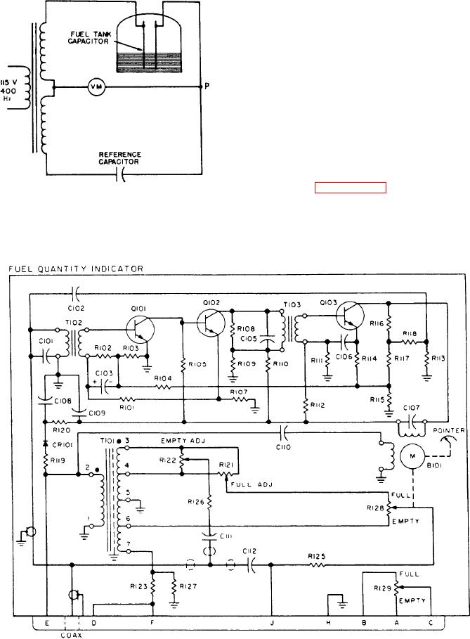
Look at figure 6-67. As the tank unit
capacitance increases or decreases, it is necessary
Figure 6-66.-Simplified capacitance bridge circuit.
to maintain the bridge circuit in a balanced
condition. This prevents the indicator motor from
Figure 6-67.-Fuel quantity indicator schematic.
6-59